- 易迪拓培训,专注于微波、射频、天线设计工程师的培养
利用E5091A的测量(测量FEM)
概述
样本程序
概述
apl_fem.vba将前端模块(FEM)测量表现为利用E5091A测量的样本程序。
如果E5071C没有4端口S参数测试仪,会出现运行时错误,因为有E5071C不能测量的参数。
-
这个VBA程序不能控制多端口测试仪E5091A-016。
对象名
模块类型
说明
mdlFemMeas
标准模块
进行FEM测量
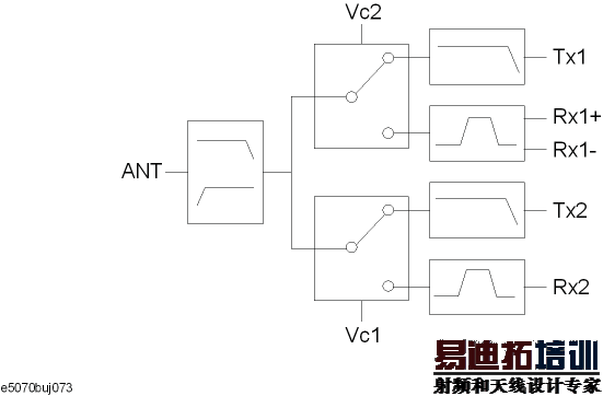
这个程序利用ECal模块来校准每个通道,然后测量如下图所示6端口双频段FEM的一些传输特征EGSM:Tx-Antenna(通道1)、EGSM:Antenna-Rx(通道2)、GSM1800:Tx-Antenna(通道3)和GSM1800:Antenna-Rx(通道4)。

当您启动程序时,将显示消息 “Connect A and T1 to ECal Module”将A和T1连接到ECal模块。将电缆从E5091A的A和T1连接到Ecal模块,然后按下OK键以校准通道1。如果由于与ECal模块的连接问题而出现故障,将显示错误消息。您可以通过点击Retry(重试)按键再次进行校准。如果想中止程序,请点击Cancel(删除)按键。以相同的方式校准通道2~4。
当校准完成时,将显示消息 “Set DUT”设置被测件。按下图所示连接被测件(FEM)和E5091A,并点击OK按键启动测量。
FEM | E5091A | |
A | ||
EGSM | Tx | T1 |
Rx+ | R1+ | |
Rx- | R1- | |
GSM1800 | Tx | T2 |
Rx | R2+ | |
Vc1 | 控制线1 | |
Vc2 | 控制线2 | |
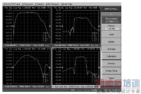
下图表明程序退出执行之后LCD屏幕的样本显示。
执行"apl_fem.vba"中的程序之后的显示实例
下面详细说明FEM的测量程序(对象名: mdlFemMeas)。添加行号只用于说明,并不在实际的程序源代码中出现。
140行到330行
设定指派给E5091A的端口1到端口4的端口和进入变量中的控制线设置(下表)
通道号 | 端口1 | 端口2 | 端口3 | 端口4 | 控制线 |
1 | A | T1 | R1+ | R1- | 0 (00000000) |
2 | A | T1 | R1+ | R1- | 2 (00000010) |
3 | A | T2 | R2+ | R2- | 0 (00000000) |
4 | A | T2 | R2+ | R2- | 1 (00000001) |
340行到660行
将下表中测量条件所需的设置设定为变量。
通道号 | 扫描范围 | 点数 | 迹线数 | 测量参数 | |
起 | 止 | ||||
1 | 400 MHz | 1.4 GHz | 51 | 1 | S12 |
2 | 880 MHz | 1 GHz
| 101 | 1 | Sds21 |
3 | 1.34 GHz | 2.34 GHz | 201 | 1 | S12 |
4 | 1.665 GHz | 2.015 GHz | 101 | 1 | S31 |
通道号 | 夹具模拟器 | 名称 | |
接通/关断 | 结构布局 | ||
1 | 关断 | E/span> E/span> | [EGSM] Tx-Antenna |
2 | 接通 | SE:1, Bal:3,4 | [EGSM] Antenna-Rx |
3 | 关断 | E/span> E/span> | [GSM1800] Antenna-Rx |
4 | 关断 | E/span> E/span> | [GSM1800] Tx-Antenna |
710行
使仪器处于预置状态。
720行
将窗口分配给左上方、右上方、左下方和右下方。
740行到1020行
对通道1~4重复以下操作,其中Ch是通道号。
780行到810行:对于ID(标识符)为1的E5091A,将指派给端口1的端口设定为Port1(Ch-1),指派给端口2的端口设定Port2(Ch-1),指派给端口3的端口设定为Port3(Ch-1),以及指派给端口4的端口设定为Port4(Ch-1)。
820行:将ID(识别符)为1的E5091A的控制线设定为Clines(Ch-1)。
860行到890行:将扫描起始值设定为Freq_star(Ch-1),扫描终止值设定为Freq_stop(Ch-1),点数设定为Nop(Ch-1),以及迹线数设定为N_tr(Ch-1)。
910行到950行:若夹具模拟器功能(启动) (Fsim (Ch-1)真实有效),则这些行将夹具模拟器功能设定到ON,器件类型设定到Dev (Ch-1),端口指派设定到Tpl (Ch-1),平衡-不平衡变换设定到ON,以及将测量参数(混合模式S参数)设定到Trc (Ch-1)。
970行:若夹具模拟器功能关断(Fsim (i)为虚假),则将测量参数(S参数)设定到Trc (Ch-1)。
990行到1010行:将名称标记设定到Ttl (Ch-1),名称显示设定到ON(启动),以及将连续起动模式设定到ON。
1040行
将触发源设定到"Bus."(总线)。
1050行到1060行
对于ID(标识符)为1的E5091A,将特征显示设定到ON和控制设定到ON。
1100行到1120行
调用功能程序: ECal_solt ( 1410行到1770行)用ECal模块执行通道1的校准(端口A和T1的全2端口校准)。若校准未正确完成,则这些行将中止程序。
1130行到1210行
以同样方式执行通道2的校准。
1260行
显示提示连接DUT(被测件)的消息,连接完成之后,等待点击OK按键。
1280行到1290行
产生起动单次扫描的触发脉冲并等待直到测量完成(用 SCPI.IEEE4882.OPC object读出1)。
1310行到1330行
对通道1~4的迹线1进行自动定标。
1350行
显示询问您是否想再次进行测量的消息。
1360行
若点击Yes(是)按键,便返回到DUT连接部分。
功能程序:ECal_solt (1410行到1770行)
1460行
清除错误排队。
1460行到1480行
显示提示将E5091A的Tset_Port与ECal模块相连的消息,连接完成之后,等待点击OK按键。
1500行
启动源自ECal_Err的出错处理程序(1670行到1740行)。若发生运行时错误,程序便转向出错处理程序。
1540行
若solt为1,便执行在通道Ch的端口Ana_port(0)上进行1端口校准的ECal命令。
1560行
若solt为2,便执行在通道Ch的端口Ana_port上进行全2端口校准的ECal命令。
1580行
若solt为3,便执行在通道Ch的端口Ana_port上进行全3端口校准的ECal命令。
1600行
若solt为4,便执行在通道Ch的端口Ana_port上进行全4端口校准的ECal命令。
1630行
将ECal_solt的返回值设定为0。
1670行到1740行
定义运行时错误处理程序。
780行到810行:对于ID(识别符)为1的E5091A,这些行将指派给端口1的端口设定为Port1 (Ch-1),指派给端口2的端口设定Port2 (Ch-1),指派给端口3的端口设定为Port3 (Ch-1),以及指派给端口4的端口设定为Port4 (Ch-1)。
1670行:从错误排队中检索出错误号和错误消息。
1680行:显示错误消息。
1700行:当点击Retry(重试)按键时,程序禁止错误处理程序运行,然后返回连接部分并重复ECal。
1720行到1730行:当点击Cancel(删除)按键时,程序将ECal_solt的返回值设定为错误号并禁止错误处理程序运行。
样本程序
FEM的测量(对象名:mdlFemMeas)
10| Sub Main()
20|
30| Dim Port1(3) As String, Port2(3) As String
40| Dim Port3(3) As String, Port4(3) As String
50| Dim Trc(3) As String, Fsim(3) As Boolean, Dev(3) As String
60| Dim Tpl(3) As Variant, Ttl(3) As String, Inp_char As String
70| Dim Freq_star(3) As Double, Freq_stop(3) As Double
80| Dim CLines(3) As Long, Nop(3) As Long, N_tr(3) As Long
90| Dim Ch As Long, Res As Long, Buff As Long, Dmy As Long
100| Dim AnaPort As Variant
110| '
120| ' E5091A Setup
130| '
140| Port1(0) = "A" '[Ch1] Port1: A
150| Port2(0) = "T1" ' Port2: T1
160| Port3(0) = "R1" ' Port3: R1+
170| Port4(0) = "R1" ' Port4: R1-
180| CLines(0) = 0 ' Control Lines: 0
190| Port1(1) = "A" '[Ch2] Port1: A
200| Port2(1) = "T1" ' Port2: T1
210| Port3(1) = "R1" ' Port3: R1+
220| Port4(1) = "R1" ' Port3: R1-
230| CLines(1) = 2 ' Control Lines: 2 (Line1:HIGH)
240| Port1(2) = "A" '[Ch3] Port1: A
250| Port2(2) = "T2" ' Port2: T2
260| Port3(2) = "R2" ' Port3: R2+
270| Port4(2) = "R2" ' Port4: R2- (Dummy)
280| CLines(2) = 0 ' Control Lines: 2 (Line1:HIGH)
290| Port1(3) = "A" '[Ch4] Port1: A
300| Port2(3) = "T2" ' Port2: T2
310| Port3(3) = "R2" ' Port3: R2+
320| Port4(3) = "R2" ' Port4: R2- (Dummy)
330| CLines(3) = 1 ' Control Lines: 1 (Line0:HIGH)
340| '
350| ' Measurement Condition
360| ' [Ch1]
370| Freq_star(0) = 400000000# ' Start frequency : 400 MHz
380| Freq_stop(0) = 1400000000# ' Stop frequency : 1.4 GHz
390| Nop(0) = 51 ' Number of points : 51
400| N_tr(0) = 1 ' Number of traces : 1
410| Fsim(0) = False ' Fixture Simulator : OFF
420| Trc(0) = "S12" ' Meas. parameter : S12
430| Ttl(0) = "[EGSM] Tx-Antenna" ' Title
440| ' [Ch2]
450| Freq_star(1) = 880000000# ' Start frequency : 880 MHz
460| Freq_stop(1) = 1000000000# ' Stop frequency : 1 GHz
470| Nop(1) = 101 ' Number of points : 101
480| N_tr(1) = 1 ' Number of traces : 1
490| Fsim(1) = True ' Fixture Simulator : ON
500| Dev(1) = "SBAL" ' Bal. Device Type : SE-Bal
510| Tpl(1) = Array(1, 3, 4) ' Topology : SE:1, Bal:3-4
520| Trc(1) = "SDS21" ' Meas. parameter : Sds21
530| Ttl(1) = "[EGSM] Antenna-Rx" ' Title
540| ' [Ch3]
550| Freq_star(2) = 1340000000# ' Start frequency : 1.34 GHz
560| Freq_stop(2) = 2340000000# ' Stop frequency : 2.34 GHz
570| Nop(2) = 201 ' Number of points : 201
580| N_tr(2) = 1 ' Number of traces : 1
590| Fsim(2) = False ' Fixture Simulator : OFF
600| Trc(2) = "S12" ' Meas. parameter : S12
610| Ttl(2) = "[GSM1800] Tx-Antenna" ' Title
620| ' [Ch4]
630| Freq_star(3) = 1665000000# ' Start frequency : 1.665 GHz
640| Freq_stop(3) = 2015000000# ' Stop frequency : 2.015 GHz
650| Nop(3) = 101 ' Number of points : 101
660| N_tr(3) = 1 ' Number of traces : 1
670| Fsim(3) = False ' Fixture Simulator : OFF
680| Trc(3) = "S31" ' Meas. parameter : S31
690| Ttl(3) = "[GSM1800] Antenna-Rx" ' Title
700|
710| SCPI.SYSTem.PRESet
720| SCPI.DISPlay.Split = "D12_34"
730|
740| For Ch = 1 To 4
750| '
760| ' E5091A Setup
770| '
780| SCPI.SENSe(Ch).MULTiplexer(1).TSET9.Port1 = Port1(Ch - 1)
790| SCPI.SENSe(Ch).MULTiplexer(1).TSET9.Port2 = Port2(Ch - 1)
800| SCPI.SENSe(Ch).MULTiplexer(1).TSET9.Port3 = Port3(Ch - 1)
810| SCPI.SENSe(Ch).MULTiplexer(1).TSET9.Port4 = Port4(Ch - 1)
820| SCPI.SENSe(Ch).MULTiplexer(1).TSET9.OUTPut.DATA = CLines(Ch - 1)
830| '
840| ' Measurement Condition
850| '
860| SCPI.SENSe(Ch).FREQuency.STARt = Freq_star(Ch - 1)
870| SCPI.SENSe(Ch).FREQuency.STOP = Freq_stop(Ch - 1)
880| SCPI.SENSe(Ch).SWEep.POINts = Nop(Ch - 1)
890| SCPI.CALCulate(Ch).PARameter.Count = N_tr(Ch - 1)
900| If Fsim(Ch - 1) = True Then
910| SCPI.CALCulate(Ch).FSIMulator.STATe = True
920| SCPI.CALCulate(Ch).FSIMulator.BALun.DEVice = Dev(Ch - 1)
930| SCPI.CALCulate(Ch).FSIMulator.BALun.TOPology.SBALanced.PPOR ts = Tpl(Ch - 1)
940| SCPI.CALCulate(Ch).FSIMulator.BALun.PARameter(1).STATe = Tr ue
950| SCPI.CALCulate(Ch).FSIMulator.BALun.PARameter(1).SBALanced. DEFine = Trc(Ch - 1)
960| Else
970| SCPI.CALCulate(Ch).PARameter(1).DEFine = Trc(Ch - 1)
980| End If
990| SCPI.DISPlay.WINDow(Ch).TITLe.DATA = Ttl(Ch - 1)
1000| SCPI.DISPlay.WINDow(Ch).TITLe.STATe = True
1010| SCPI.INITiate(Ch).CONTinuous = True
1020| Next Ch
1030|
1040| SCPI.TRIGger.SEQuence.Source = "BUS"
1050| SCPI.SENSe.MULTiplexer(1).DISPlay.STATe = True
1060| SCPI.SENSe.MULTiplexer(1).STATe = True
1070| '
1080| ' Calibration
1090| '
1100| AnaPort = Array(1, 2)
1110| Res = ECal_Solt(1, 2, AnaPort, "A and T1")
1120| If Res <> 0 Then GoTo Prg_end
1130| AnaPort = Array(1, 3, 4)
1140| Res = ECal_Solt(2, 3, AnaPort, "A, R1+ and R1-")
1150| If Res <> 0 Then GoTo Prg_end
1160| AnaPort = Array(1, 2)
1170| Res = ECal_Solt(3, 2, AnaPort, "A and T2")
1180| If Res <> 0 Then GoTo Prg_end
1190| AnaPort = Array(1, 3)
1200| Res = ECal_Solt(4, 2, AnaPort, "A and R2+")
1210| If Res <> 0 Then GoTo Prg_end
1220| '
1230| ' Measurement
1240| '
1250| Meas_Start:
1260| MsgBox "Connect DUT.", vbOKOnly, "Measurement"
1270|
1280| SCPI.TRIGger.SEQuence.SINGle
1290| Dmy = SCPI.IEEE4882.OPC
1300|
1310| For Ch = 1 To 4
1320| SCPI.DISPlay.WINDow(Ch).TRACe(1).Y.SCALe.AUTO
1330| Next Ch
1340|
1350| Buff = MsgBox("Do you make another measurement?", vbYesNo)
1360| If Buff = vbYes Then GoTo Meas_Start
1370|
1380| Prg_end:
1390| End Sub
1400|
1410| Function ECal_Solt(Ch As Long, Solt As Long, AnaPort As Variant, TsetPort As String) As Long
1420| Dim Err_info As Variant
1430| Dim Buff As Long
1440|
1450| Ecal_start:
1460| SCPI.IEEE4882.CLS
1470|
1480| MsgBox "Connect " + TsetPort + " to ECal Module."
1490|
1500| On Error GoTo Ecal_err
1510|
1520| Select Case Solt
1530| Case 1
1540| SCPI.SENSe(Ch).CORRection.COLLect.ECAL.SOLT1 = AnaPort(0)
1550| Case 2
1560| SCPI.SENSe(Ch).CORRection.COLLect.ECAL.SOLT2 = AnaPort
1570| Case 3
1580| SCPI.SENSe(Ch).CORRection.COLLect.ECAL.SOLT3 = AnaPort
1590| Case 4
1600| SCPI.SENSe(Ch).CORRection.COLLect.ECAL.SOLT4 = AnaPort
1610| End Select
1620|
1630| ECal_Solt = 0
1640| GoTo Ecal_end
1650|
1660| Ecal_err:
1670| Err_info = SCPI.SYSTem.Error
1680| Buff = MsgBox("Error: " + Err_info(1), vbRetryCancel)
1690| If Buff = vbRetry Then
1700| Resume Ecal_start
1710| Else
1720| ECal_Solt = Err_info(0)
1730| Resume Ecal_end
1740| End If
1750|
1760| Ecal_end:
1770| End Function


