- 易迪拓培训,专注于微波、射频、天线设计工程师的培养
LabVIEW学习笔记——第一个程序:波形显示
录入:edatop.com 点击:
首先,新建一个VI项目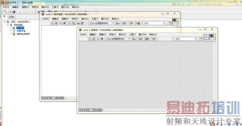 接着,在前面板上拖放一个显示面板。如图所示
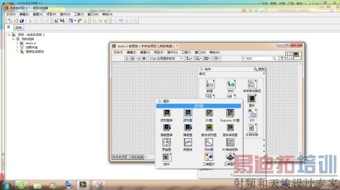

最后,程序结构的处理,我们希望程序可以无限次的执行,直到我们要求它停止为止。在后面板(也就是程序框图面板)空白处右击,在“结构”中选择“While 循环”,循环的终止条件选择创建输入控件。至此全部完成。第一个程序会有一些瑕疵,以后改进!
然后,按住CTRL+E切换到程序面板进行程序框图编辑。右键程序面板空白处,选择“信号处理”模块下的“信号生成”下的“基本函数发生器
”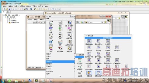
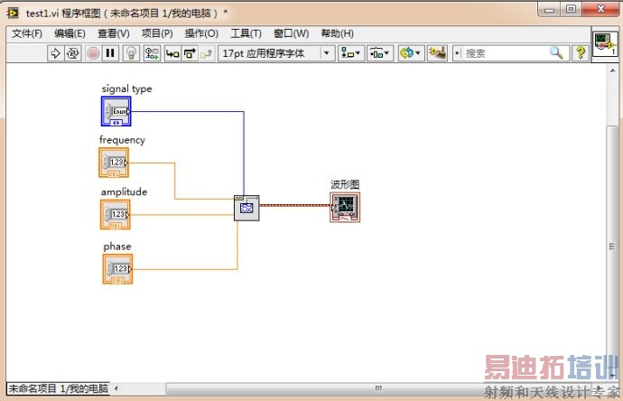
右键”基本函数发生器“上的”信号类型“、“频率”、“幅值”、“相位”端口,选择创建输入控件。最后将其“信号输出”端口和波形图的输入相连。
最后,程序结构的处理,我们希望程序可以无限次的执行,直到我们要求它停止为止。在后面板(也就是程序框图面板)空白处右击,在“结构”中选择“While 循环”,循环的终止条件选择创建输入控件。至此全部完成。第一个程序会有一些瑕疵,以后改进!