- 易迪拓培训,专注于微波、射频、天线设计工程师的培养
Maxim 71M6541F单相电表解决方案
录入:edatop.com 点击:
Maxim公司的71M6541D/71M6541F/71M6541G/71M6542F/71M6542G是Teridian™第四代单相电表SoC,集成了5MHz 8051兼容的MPU核,带数字温度补偿的低功耗RTC,闪存和LCD驱动器.转换技术采用22位Delta-Sigma ADC,三/四个模拟输入,数字温度补偿,精密基准电压,以及支持多种测量应用的32位计算引擎(CE),外接元件非常少.2000:1电流范围的精度为0.1%,超出IEC 62053/ANSI C12.20 标准,可选择差分模式的两个电报挂号流传感器输入.本文介绍了71M6541F主要特性,功能方框图,与本地传感器和71M6x01隔离传感器的连接图以及演示板DB6541 REV2.0特性,和调试板基本连接图,电路图,材料清单和PCB布局图.
The 71M6541D/71M6541F/71M6541G/71M6542F/71M6542G are Teridian™ 4th-generation single-phase metering SoCs with a 5MHz 8051-compatible MPU core, low-power RTC with digital temperature compensation, flash memory, and LCD driver. Our Single Converter Technology® with a 22-bit delta-sigma ADC, three or four analog inputs, digital temperature compensation, precision voltage reference, and a 32-bit computation engine (CE) supports a wide range of metering applications with very few external components.
The 71M6541/2 devices support optional interfaces to the Teridian 71M6x01 series of isolated sensors, which offer BOM cost reduction, immunity to magnetic tamper, and enhanced reliability. Other features include an SPI interface, advanced power management, ultra-low-power operation in active and battery modes, 3/5KB shared RAM and 32/64/128KB of flash memory that can be programmed in the field with code and/or data during meter operation and the ability to drive up to six LCD segments per SEG driver pin. High processing and sampling rates combined with differential inputs offer a powerful metering platform for residential meters.
A complete array of code development tools, demonstration code, and reference designs enable rapid development and certification of meters that meet all ANSI and IEC electricity metering standards worldwide.
71M6541F主要特性:
• 0.1% Accuracy Over 2000:1 Current Range
• Exceeds IEC 62053/ANSI C12.20 Standards
• Two Current Sensor Inputs with Selectable Differential Mode
• Selectable Gain of 1 or 8 for One Current Input to Support Shunts
• High-Speed Wh/VARh Pulse Outputs with Programmable Width
• 32KB Flash, 3KB RAM (71M6541D)
• 64KB Flash, 5KB RAM (71M6541F/42F)
• 128KB Flash, 5KB RAM (71M6541G/42G)
• Up to Four Pulse Outputs with Pulse Count
• Four-Quadrant Metering
• Digital Temperature Compensation:
- Metrology Compensation
- Accurate RTC for TOU Functions with Automatic Temperature Compensation for Crystal in All Power Modes
• Independent 32-Bit Compute Engine
• 46-64Hz Line Frequency Range with the Same Calibration
• Phase Compensation ( 10 )
• Three Battery-Backup Modes:
- Brownout Mode (BRN)
- LCD Mode (LCD)
- Sleep Mode (SLP)
• Wake-Up on Pin Events and Wake-On Timer
• 1μA in Sleep Mode
•Flash Security
•In-System Program Update
•8-Bit MPU (80515), Up to 5 MIPS
•Full-Speed MPU Clock in Brownout Mode
•LCD Driver:
- Up to 6 Commons/Up to 56 Pins
•5V LCD Driver with DAC
•Up to 51 Multifunction DIO Pins
•Hardware Watchdog Timer (WDT)
•I2C/MICROWIRE®EEPROM Interface
•SPI Interface with Flash Program Capability
•Two UARTs for IR and AMR
•IR LED Driver with Modulation
•Industrial Temperature Range
•64-Pin (71M6541D/F/G) and 100-pin (71M6542F/G) Lead(Pb)-Free LQFP Package
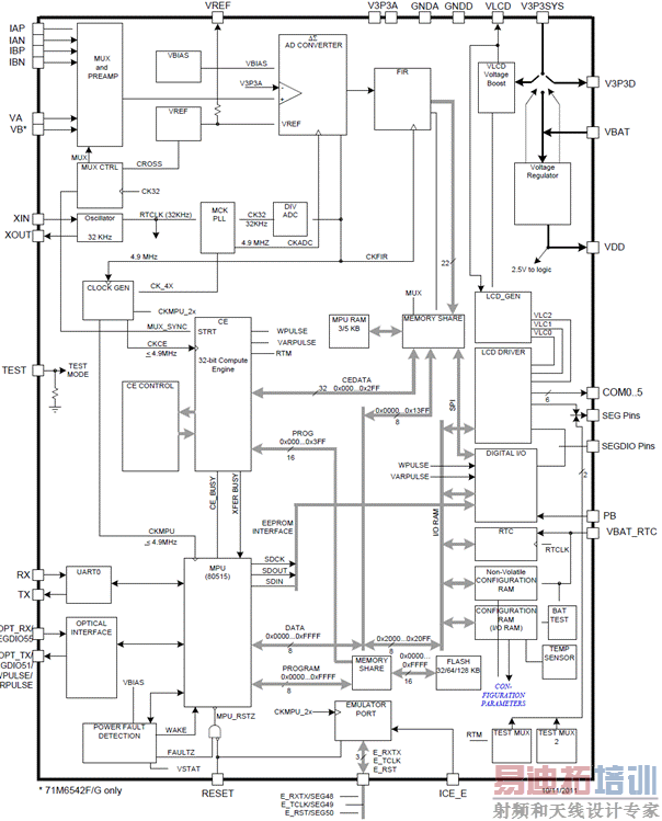
图1.71M6541F功能框图
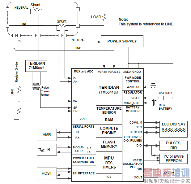
图2.71M6541D/F/G和本地传感器连接图
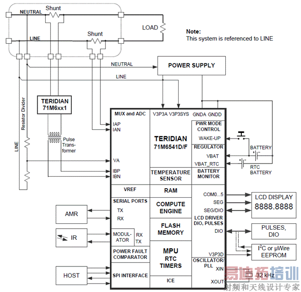
图3.71M6541D/F/G和71M6x01隔离传感器连接图
71M6541F演示板DB6541 REV2.0
The Teridian Semiconductor Corporation (TSC) DB6541 REV2.0 Demo Board is a demonstration board for evaluating the 71M6541F device for single-phase electronic power metering applications in conjunction with the Remote Sensor Interface. It incorporates a 71M6541F integrated circuit, a 71M6101 Remote Interface IC, peripheral circuitry such as a serial EEPROM, emulator port, and on-board power supply as well as a companion Debug Board that allows a connection to a PC through a RS-232 port. The Demo Board allows the evaluation of the 71M6541F energy meter chip for measurement accuracy and overall system use.
The board is pre-programmed with a Demo Program (Demo Code) in the FLASH memory of the 71M6541F IC. This embedded application is developed to exercise all low-level function calls to directly manage the pe-ripherals, flash programming, and CPU (clock, timing, power savings, etc.).
The 71M6541F IC on the Demo Board is pre-programmed and pre-calibrated for the 50 μΩ or 120 μΩ shunt shipped with the board. The Demo Board may also be used for operation with a CT after hardware modifica-tions that can be easily performed by the user. This configuration will require a different version of the Demo Code.
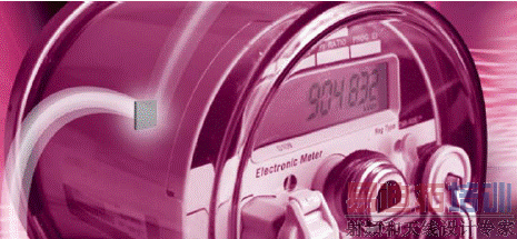
图4.单相电表外形图
演示板包括:
• Demo Board DB6541 REV 3.0 containing one 71M6601 or 71M6201 Remote Sensor Interface and one 71M6541F IC with pre-loaded demo program
• 5VDC/1,000mA universal wall transformer with 2.5mm plug (Switchcraft 712A compatible)
• USB cable
• CD-ROM containing documentation (data sheet, board schematics, BOM, layout), Demo Code (sources and executable), and utilities.
• ANSI base with 50 μΩ shunt resistor (optional, for ANSI kits only) or two 120 μΩ shunt resistors
The Demo Board contains all circuits necessary for operation as a meter, including display, calibration LEDs, and internal power supply. The Debug Board uses a separate power supply, and is optically isolated from the Demo Board. It interfaces to a PC through the USB connector.
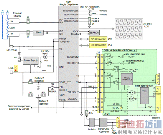
图5.Teridian DB6541 REV2.0 演示板和调试板基本连接图
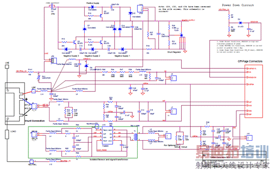
图6.DB6541 REV 3.0 演示板电路图(1)
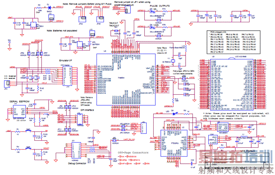
图7.DB6541 REV 3.0 演示板电路图(2)
DB6541 REV 3.0 演示板材料清单(BOM):
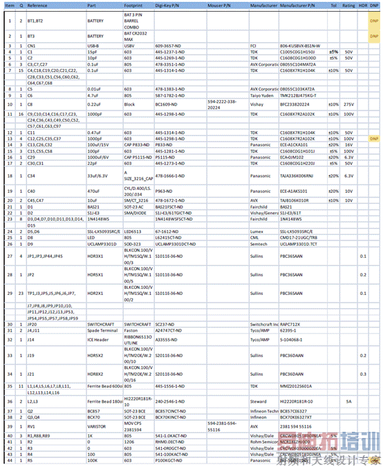
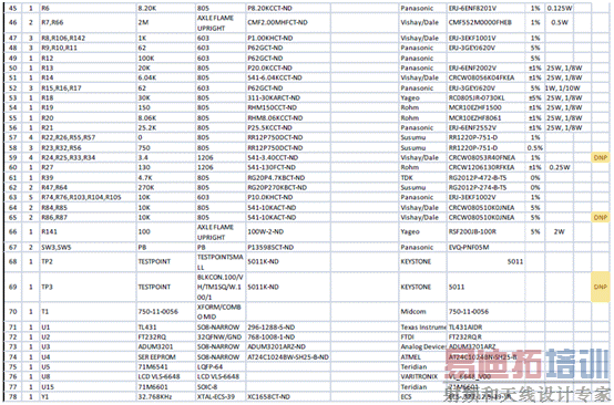
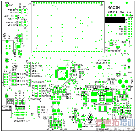
图8.DB6541 REV 3.0 演示板PCB元件布局图(顶层)
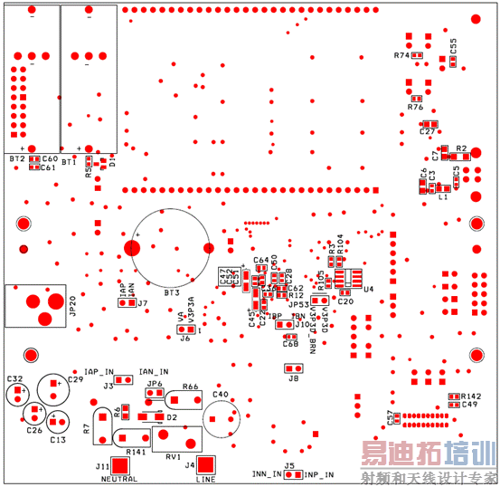
图9.DB6541 REV 3.0 演示板PCB元件布局图(底层)
详情请见:
 71M6541D-71M6542G[1].pdf(2.17 MB, 下载次数: 0)
和
 71M6541F-DB[1].pdf(1.98 MB, 下载次数: 0)
来源:网络
The 71M6541D/71M6541F/71M6541G/71M6542F/71M6542G are Teridian™ 4th-generation single-phase metering SoCs with a 5MHz 8051-compatible MPU core, low-power RTC with digital temperature compensation, flash memory, and LCD driver. Our Single Converter Technology® with a 22-bit delta-sigma ADC, three or four analog inputs, digital temperature compensation, precision voltage reference, and a 32-bit computation engine (CE) supports a wide range of metering applications with very few external components.
The 71M6541/2 devices support optional interfaces to the Teridian 71M6x01 series of isolated sensors, which offer BOM cost reduction, immunity to magnetic tamper, and enhanced reliability. Other features include an SPI interface, advanced power management, ultra-low-power operation in active and battery modes, 3/5KB shared RAM and 32/64/128KB of flash memory that can be programmed in the field with code and/or data during meter operation and the ability to drive up to six LCD segments per SEG driver pin. High processing and sampling rates combined with differential inputs offer a powerful metering platform for residential meters.
A complete array of code development tools, demonstration code, and reference designs enable rapid development and certification of meters that meet all ANSI and IEC electricity metering standards worldwide.
71M6541F主要特性:
• 0.1% Accuracy Over 2000:1 Current Range
• Exceeds IEC 62053/ANSI C12.20 Standards
• Two Current Sensor Inputs with Selectable Differential Mode
• Selectable Gain of 1 or 8 for One Current Input to Support Shunts
• High-Speed Wh/VARh Pulse Outputs with Programmable Width
• 32KB Flash, 3KB RAM (71M6541D)
• 64KB Flash, 5KB RAM (71M6541F/42F)
• 128KB Flash, 5KB RAM (71M6541G/42G)
• Up to Four Pulse Outputs with Pulse Count
• Four-Quadrant Metering
• Digital Temperature Compensation:
- Metrology Compensation
- Accurate RTC for TOU Functions with Automatic Temperature Compensation for Crystal in All Power Modes
• Independent 32-Bit Compute Engine
• 46-64Hz Line Frequency Range with the Same Calibration
• Phase Compensation ( 10 )
• Three Battery-Backup Modes:
- Brownout Mode (BRN)
- LCD Mode (LCD)
- Sleep Mode (SLP)
• Wake-Up on Pin Events and Wake-On Timer
• 1μA in Sleep Mode
•Flash Security
•In-System Program Update
•8-Bit MPU (80515), Up to 5 MIPS
•Full-Speed MPU Clock in Brownout Mode
•LCD Driver:
- Up to 6 Commons/Up to 56 Pins
•5V LCD Driver with DAC
•Up to 51 Multifunction DIO Pins
•Hardware Watchdog Timer (WDT)
•I2C/MICROWIRE®EEPROM Interface
•SPI Interface with Flash Program Capability
•Two UARTs for IR and AMR
•IR LED Driver with Modulation
•Industrial Temperature Range
•64-Pin (71M6541D/F/G) and 100-pin (71M6542F/G) Lead(Pb)-Free LQFP Package

图1.71M6541F功能框图

图2.71M6541D/F/G和本地传感器连接图

图3.71M6541D/F/G和71M6x01隔离传感器连接图
71M6541F演示板DB6541 REV2.0
The Teridian Semiconductor Corporation (TSC) DB6541 REV2.0 Demo Board is a demonstration board for evaluating the 71M6541F device for single-phase electronic power metering applications in conjunction with the Remote Sensor Interface. It incorporates a 71M6541F integrated circuit, a 71M6101 Remote Interface IC, peripheral circuitry such as a serial EEPROM, emulator port, and on-board power supply as well as a companion Debug Board that allows a connection to a PC through a RS-232 port. The Demo Board allows the evaluation of the 71M6541F energy meter chip for measurement accuracy and overall system use.
The board is pre-programmed with a Demo Program (Demo Code) in the FLASH memory of the 71M6541F IC. This embedded application is developed to exercise all low-level function calls to directly manage the pe-ripherals, flash programming, and CPU (clock, timing, power savings, etc.).
The 71M6541F IC on the Demo Board is pre-programmed and pre-calibrated for the 50 μΩ or 120 μΩ shunt shipped with the board. The Demo Board may also be used for operation with a CT after hardware modifica-tions that can be easily performed by the user. This configuration will require a different version of the Demo Code.

图4.单相电表外形图
演示板包括:
• Demo Board DB6541 REV 3.0 containing one 71M6601 or 71M6201 Remote Sensor Interface and one 71M6541F IC with pre-loaded demo program
• 5VDC/1,000mA universal wall transformer with 2.5mm plug (Switchcraft 712A compatible)
• USB cable
• CD-ROM containing documentation (data sheet, board schematics, BOM, layout), Demo Code (sources and executable), and utilities.
• ANSI base with 50 μΩ shunt resistor (optional, for ANSI kits only) or two 120 μΩ shunt resistors
The Demo Board contains all circuits necessary for operation as a meter, including display, calibration LEDs, and internal power supply. The Debug Board uses a separate power supply, and is optically isolated from the Demo Board. It interfaces to a PC through the USB connector.

图5.Teridian DB6541 REV2.0 演示板和调试板基本连接图

图6.DB6541 REV 3.0 演示板电路图(1)

图7.DB6541 REV 3.0 演示板电路图(2)
DB6541 REV 3.0 演示板材料清单(BOM):


图8.DB6541 REV 3.0 演示板PCB元件布局图(顶层)

图9.DB6541 REV 3.0 演示板PCB元件布局图(底层)
详情请见:
 71M6541D-71M6542G[1].pdf(2.17 MB, 下载次数: 0)
和
 71M6541F-DB[1].pdf(1.98 MB, 下载次数: 0)
来源:网络

