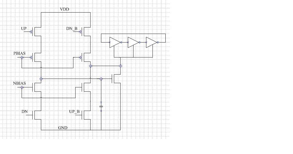
大家来讨论一下这个CP_LPF_VCO电路
录入:edatop.com 阅读:
电路图如下图,UP和DN分别是PFD出来的信号,UP_B和DN_B是它们的反相信号。请问这个是个什么结构啊,补偿的零点是辅助支路提供的么?

感觉上这个电路图不对,应该把UP和UP_B互换一下才可以工作。同时,这是个简化了的环路滤波器,我觉得没有补偿的零点,辅助支路的作用和主支路的作用差不多。
The NMOS is not for compensation or other purpose, it is mainly used to provide an inverting stage( like a inverter), so the polarity of the UP,DN, UP_B, DN_B are the same, I think it may enhance the accuracy for the current injection since the total current is combined with two branches
2# northfish
这里我没有说清楚,UP是低有效,DN是高有效,所以UP和UP_B是正确的。
那如果不提供零点,这个CP_PLL是II型系统,在原点处有两个极点,那系统会稳定么?
3# jesseyu
I agree with you , but how does it make the CP_PLL loop stable without a zero? This is II-type system.
申明:网友回复良莠不齐,仅供参考。如需专业解答,请学习本站推出的微波射频专业培训课程。

