- 易迪拓培训,专注于微波、射频、天线设计工程师的培养
Add capacitive sensing to a digital handset
With this in mind, manufacturers are focusing on innovative techniques for replacing space-consuming buttons and switches without compromising the cell-phone user interface (CPUI). A powerful reduction technique adopts capacitive sensing into the CPUI.
Capacitive sensing enables lower cost, robustness, flexibility, and an intuitive CPUI without breaking compatibility with existing form factors and feature sets. Capacitive sensing functions can be combined with other standard functions, such as white LED driving and battery charging to further drive cost down.
A typical mid-market CPUI consists of several buttons, switches, and displays. To obtain basic functionality, a CPUI only requires an alphanumeric keypad, display, and possibly a power switch. But how many consumers are satisfied with basic functionality? Today''s manufacturers design phones with the ability to web browse, send text messages, take pictures, and even store and play back music.
Increase the CPUI
To support these features, manufacturers must add functionality to the CPUI that enables simple and intuitive access to these functions. The result of the additional functionality is a CPUI that''s either physically larger or increasingly more complex. Unfortunately, consumers are also drawn to simpler and slimmer cell phones. How can cell phone makers solve this consumer-driven paradox? One possibility is to replace the traditional buttons and switches with capacitive sensors, which can replace both digital switches and linear sliders, two common characteristics of today''s CPUIs.
In its basic form, a capacitive sensor is a pair of adjacent plates, with an inherent capacitance between them. This capacitance is directly proportional to the plates'' thickness and inversely proportional to the distance between them. Ideally, this is the only measurable capacitance of the sensor.
A conductive object, such as a finger, when placed in close proximity to the two plates, adds a parallel capacitance to the inherent capacitance. The measurable capacitance is now the summation of the inherent and finger-to-sensor coupling capacitance. Place a finger on the capacitive sensor, and the capacitance increases. Remove the finger, and it decreases. Add intelligence to measure the change in capacitance, and it''s possible to determine the presence or absence of a finger.
Tale of two traces
A common electrical pcb implementation of a capacitive sensor consists of two adjacent finitely spaced copper pads or traces. This is a basic capacitive digital switch. Likewise, a linear slider consists of an array of capacitive sensors on the pcb. Typically, one of the sensor''s copper plates is grounded, leaving only one active plate. In practice, fringing capacitances add to the sensor''s inherent capacitance and yield gross typical values between 10 and 30 pF. Typical finger coupling capacitance values are between 1 and 2 pF. The challenge in implementing a capacitive sensor involves designing a circuit that can measure a 3% capacitance change introduced by a finger.
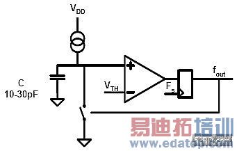
A relaxation oscillator is an effective and simple circuit for measuring capacitance (Fig. 1). This circuit consists of four components: a synchronous comparator, current source, discharge switch, and the capacitive sensor.
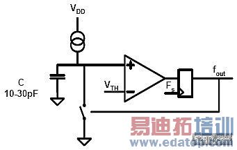
Initially, the discharge switch is open, and the current source linearly charges the sensor. The voltage on the sensor ramps positively until it exceeds the comparator''s threshold. The comparator''s output transitions from low to high, causing the discharge switch to close. The sensor quickly discharges through this low impedance path to ground. The process causes the comparator''s output to transition from high to low, and the cycle repeats. The output frequency (fout) is dependent on the charging current and capacitive sensor value as illustrated by:

Typical designs set the oscillator''s frequency between 20 and 200 kHz. The frequency is then fed into an intelligent measurement circuit. By measuring the change in the frequency, it''s possible to determine the presence or absence of a finger. There are two widely accepted methods for measuring the frequency of the relaxation oscillator. One method measures frequency; the other method measures period.
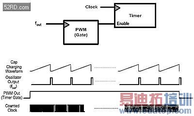
Frequency measurement involves measuring the relaxation oscillator frequency for a fixed time period using a gated timer (Fig. 2). The timer is read to determine the number of counts accumulated during the fixed period. This method works well for slow frequencies where the discharge time of the capacitive sensor is negligible compared to the oscillator period.
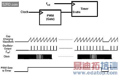
Period measurement uses the oscillator frequency as a gate for a pulse-width modulator (PWM). The timer is clocked by a faster frequency than that of the relaxation oscillator (Fig. 3). The faster the timer clock, the better the resolution of the measured capacitance. Either method can be easily implemented with traditional 555 timers or more complex microcontrollers. Because an intelligent software algorithm is needed to determine the presence or absence of a finger, a microcontroller-based solution seems more elegant.
Cypress'' PSoC Mixed-Signal Array CY8C21x34 and CY8C24794 families contain CapSense technology that enables cost-effective and straightforward capacitive sensing designs through a relaxation oscillator topology. This includes multiple precision timers and counters, a comparator with automatic connection to a discharge switch, a programmable current source, and a wide analog multiplexer that lets every pin act as a potential capacitive sensor (Fig. 4).
Software is required to determine the presence or absence of a finger on a digital switch or the finger''s precise location on a linear slider. Both digital switches and linear sliders must convert the count value from the measurement circuitry into a finger detection decision. To further calculate the finger location on a linear slider requires a weighted average of the capacitance of a multiple-sensor array. A two-element slider has an inherent one element LSB. If the finger is on the slider, it can be on either element zero, one, or even both. However, finger position is often needed in a resolution greater than the physical pitch of the individual capacitive sensor, and therefore the second function also incorporates an interpolation algorithm. Interpolation decreases the LSB from one element to a half, quarter, or a sixteenth. Interpolation is key to implementing smooth capacitive linear sliders.
Capacitive digital switches can easily replace the basic alphanumeric keypad and power switch in today''s CPUIs. The advantage of this replacement scheme is two-fold: the CPUI''s physical depth and overall cost is reduced. With capacitive sensing, multiple complex and basic CPUI functions can be incorporated into one capacitive linear slider. One slider can provide a scrolling function for web browsing or address book traversing, volume control, and brightness control. All these features can be implemented in less physical space than traditional CPUIs.
A two-dimensional linear slider can transform a traditional CPUI into a touchpad, similar to those found on many of today''s laptop computers. A mid-market cell phone with a touchpad CPUI can offer more accessible features, such as cursor control. Another feature of a capacitive touchpad is its ability to adapt to various geometric form factors.
Handling environmental isolation
One problem that must be addressed is environmental isolation. A cell phone''s lifespan would be compromised if the capacitive sensors were allowed direct contact with the finger or other environmental hazards. Therefore, it''s necessary to separate the capacitive sensors from the environment with an insulating material. Laptop makers commonly use Mylar labels or plastic covers to provide the necessary isolation. Unfortunately, this insulating material lowers the coupling capacitance between a finger and the sensor. Lower coupling capacitance equals lower finger sensitivity.
A typical insulating material is 20 mils thick. Maximum thickness values are around 2 mm. Beyond that, the capacitive sensor is too insensitive for finger detection. While the insulation layer reduces overall sensitivity, it also provides avenues of creativity for phone makers. They can hide the two-dimensional sensors behind flashy plastic covers.
Consider a plastic cover with a silk-screened alphanumeric pattern that provides basic phone functionality. Silk-screen a scroll bar along the perimeter of the cover and it''s possible to realize the advanced functions. The same capacitive touchpad plus a plastic covers equals multiple CPUI functions.
Capacitive sensing functions can also be combined with other standard phone functions to lower the phone''s cost, such as driving white LEDs in the phone''s display and charging the internal battery. Functions that were traditionally handled by separate MCUs can be handled by one MCU.
About the author
Andrew Page is a senior applications engineer at Cypress Semiconductor. He received his BSEE from Seattle Pacific University. He can be reached at aep@cypress.com.

