The traditional way to control the output of multiple LEDs is to dedicate a pulse width modulation (PWM) controller to each LED and use the controller to transform the input voltage to a current that supplies the LED. Often voltage controlled PWM controllers are used for this purpose. A current sense resistor is placed in series with the LED that feeds a voltage back to the controller. In essence, the controller is operating in a voltage mode holding the sample voltage constant, thereby, maintaining a constant current. This typical arrangement is shown in Figure 1.
 Figure 1. Typical PWM controller developing a constant current
In Figure 1, R1 samples the current flowing in D1. The resulting voltage is compared to a reference voltage in the PWM controller, which closes the switch for a percentage of each clock cycle. Just enough energy is transferred to the output during the time the switch is closed to produce the desired current that is sensed in R1. If too much or too little energy is transferred, the voltage across R1 will increase or decrease and change the time the switch is closed. The result of this is a closed loop system that maintains a voltage across the R1 equal to the reference voltage, and delivers a constant current to the diode D1 given by:

.
The difficulty with this approach is that when there are several LEDs in an application, each LED requires its own controller and the associated cost and space. Also, because the controllers are designed to deliver substantial currents, they typically use large values of output capacitance, which limits how quickly they can respond to control commands.
A common application that uses multiple color LEDs is the creation of white light. In this case, at least Red, Green and Blue LEDs are required. Often in these applications a forth or even a fifth LED is included in an attempt to obtain a particular hue of white. With a typical set of three controllers, the LED currents are set in specific ratios so that 50 to 64 percent of the light is Green, 25 to 40 percent Red, and five to 15 percent is Blue. This mix mimics the spectral ratios of red, green and blue in white light. This approach requires the use of three separate PWM controllers and their associated cost. Each controller powers one LED color with dimming accomplished by changing the individual PWM duty cycles.
A simpler approach
An alternate approach is to develop a single current and place the LEDs in a series string. The brightness then can be controlled by placing a field effect transistor (FET) switch in parallel with each LED. When the FET is turned on, the common current is shunted around the LED turning it off. A control mechanism is used to turn each LED off for a controlled percentage of each clock cycle. This approach is shown in Figure 2 where a string of three LEDs share a common current and are individually adjusted by parallel FET switches. An implementation of this approach is shown in block form in Figure 3.
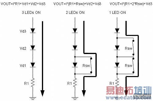
Figure 2. LED control using a PWM current shunt technique
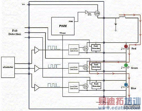
Figure 3. Block diagram of the shunt approach
In this approach, the single controller provides a single current that is controlled by a sense resistor at the bottom at the LED string. The system is controlled by an external microcontroller that drives the level shifted drivers that control the shunt FETS. Brightness is controlled by adjusting the percentage of time each FET allows current to flow through its respective LED. The ability to use the processing power of a very inexpensive controller to overcome some of the shortcomings of the LEDs is a significant benefit of this approach. For example Blue LEDs are less efficient and are often run at higher current to achieve brightness balance. This same result can be achieved by appropriately scaling the duty cycles of the FETs to solve this issue. Since it is current density that controls light output, a supplementary method of compensating for brightness imbalances is to place the larger of two LED diodes in parallel where the inherent light of a particular LED color is weak. A circuit has been built to examine this concept and is shown in Figure 4.
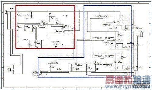
Figure 4. Schematic of a three LED control circuit
The controller in this circuit is a TPS40200 that is used with a pair of parallel current sensing resistors (R11 and R5) to maintain a constant output current across a series string of three LEDs. In this case, the circuit is set up to deliver 700 mA of output current. Each of the three shunt FETs is controlled by a floating driver that can be driven by standard logic, and yet, can control FETs that are at varying voltages above ground.
The circuit’s output voltage is determined by the forward voltages of the LEDs and the voltage across the sense resistors. In this case, the output voltage was about 10.5 volts.
Since this is a constant current system, there is no need for large output capacitance at the PWM output. This not only saves component cost, but also helps the system respond quickly to output voltage changes. These changes arise as the FETs turn on, and the voltage drops change from the drop of an LED to the smaller drop caused by the Rdson of the FET. Figure 5 below illustrates this effect as one channel is turned on and off. As the figure shows, the transitions are smooth with no over shoot or instability in the PWM controller’s control loop.
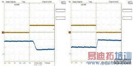 Figure 5. Logic input to LED output voltage transitions
By controlling the LED string with digital inputs, the user can use a microprocessor to easily create lighting effects from simple dimming, to color changes, to light directional steering. With relatively simple additional circuits, the user can also use this approach to achieve compensation for LED brightness that occurs over temperature and time. In particular, others have shown that with the use of an inexpensive processor and temperature sensing, the temperature drift of RED LEDs, which is approximately 40 percent in luminous flux over 50 degrees C, can be accommodated by proportionally changing the Red LED’s duty cycle. Additionally, aging effects can be handled by periodically sampling the individual LEDs with a single light sensor, and comparing luminosity results with previously stored values kept in EEPROM. The processor can then adjust duty cycles to restore color balance and maintain the desired color. This circuit approach provides a simple way to control multiple LEDs from a processor. Doing so enables the solutions to LED aging and variability to be implemented in a more cost-effective manner.
. 


