- 易迪拓培训,专注于微波、射频、天线设计工程师的培养
Create a flexible EDGE data receiver(Part 2)
EDGE data receiver
A typical EDGE handset receiver consists of an RF front end, a mixed-signal portion, and a baseband receiver. The RF portion impacts the baseband receiver''s performance and design by various imperfections/effects it introduces, including noise, dc offset (DCO), local oscillator (LO) frequency error, mixer phase and amplitude imbalance, and LO phase noise. The mixed-signal portion of the chain samples the received continuous signal and provides channel selectivity using a digital receive (RX) filter.
The challenge in RX filter design is to find the balance between adjacent channel suppression and desired signal distortion—the lower the RX filter''s cutoff frequency, the higher adjacent channel suppression that can be achieved. On the other hand, lower cutoff frequency results in higher distortion of the desired signal, and therefore worse reference sensitivity and co-channel interference performance of the receiver.
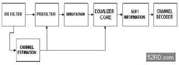
The EDGE data receiver resides in the terminal''s baseband section and consists of several functional blocks: synchronization and channel-impulse response (CIR) estimation block, a prefilter, derotation block, equalizer core, soft information block, and channel decoder (Fig. 1).

The synchronization and CIR estimation block acquires the initial synchronization, finding the position of the training sequence in the received data buffer, and consequently the CIR estimate. GSM/EDGE system dynamics require that CIR estimation be repeated every burst. The CIR changes slowly enough over the duration of one burst so that adaptive CIR estimation within a burst isn''t necessary, apart from phase and frequency error correction.
A CIR estimate is required to compute prefilter and equalizer taps, and is essential for reliable operation of an EDGE receiver. Cross-correlation-based approaches previously used in GSM/GPRS aren''t adequate for EDGE to secure accurate CIR estimates in long channels (HT with seven CIR taps) and will result in relatively high CIR estimation error. Therefore, it''s desirable to perform more complex Least Squares (LS) based estimation. Formulation of an LS CIR estimation problem allows the use of side information of non-white noise correlation in CIR estimation [1], providing up to 1.6 dB reduction in CIR estimation error variance in short channels.
Regardless of the CIR estimation algorithm used, it''s necessary to establish several related parameters, such as the number of CIR taps, and the relation of the CIR with respect to the position of the largest magnitude CIR tap (i.e., whether there are any significant taps before the largest magnitude tap). As GSM and EDGE operate in channel profiles of very different lengths (three to eight taps) the selection of the number of CIR taps has profound influence on receiver performance. In short channels (static, RA, TU), inclusion of unnecessary small magnitude taps leads to a deterioration in performance. Thus, it''s advantageous to detect and remove these low magnitude taps from the CIR estimate. The simplest way of doing this is to eliminate all those taps whose estimates have a magnitude lower than the expected variance of the CIR tap estimation.
Dc offset estimation and compensation is essential for EDGE receiver performance. While for GMSK modulation simple averaging of the received burst may be sufficient for dc estimation and compensation, the error introduced by this procedure is too large for satisfactory performance with the 8PSK modulation used in EDGE. In EDGE 8PSK modulated MCS, it''s necessary to resort to joint LS CIR and DCO estimation [2].
Equalization for EDGE is in the center of data receiver design and performance considerations. The EDGE standard presents a unique set of challenges. Nonlinear equalization techniques are required to provide required performance, however complexity constraints eliminate Maximum Likelihood Sequence Estimation (MLSE) equalization technique as a viable solution. Alternatively side, the simplest sub-optimal equalizer, the Decision Feedback Equalizer (DFE), has inadequate performance. The two suboptimal equalization algorithms most frequently proposed for use with EDGE 8PSK channels are the Delayed Decision Feedback Sequence Estimator (DDFSE) and Reduced State Sequence Estimator (RSSE) [3].
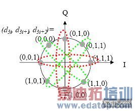
The DDFSE divides the CIR into two parts, one of which is equalized using the MLSE type receiver while the other is accounted for by subtracting the expected received signal value due to those taps. The DDFSE can be viewed as a specific case of RSSE, which assigns to every tap a number of states that''s a power of two by grouping the symbols. For example, with EDGE 8PSK, we may use RSSE (2,1,1) to further reduce the equalizer''s complexity by dividing eight possible 8PSK symbols into only two groups, with four symbols each (Fig. 2). This reduces the number of states in the trellis and consequently reduces the computational complexity, so RSSE (2,2,1) has only four states.

To insure adequate performance of suboptimal schemes, it''s essential to shape the impulse response. The prefilter modifies the CIR ensuring that energy is concentrated in post-cursors and the resulting combined CIR is minimum phase which ensures better equalizer performance. Selection of prefiltering length is another tradeoff between the performance and complexity.
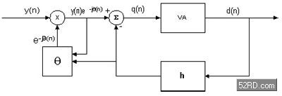
Note that equalization technique, although in the heart of data receiver design, provides only partial insight into overall solution. The overall data receiver solution is sensitive to imperfections of the receiver front-end, channel estimation quality, selection of soft-decision, and other synchronization parameters. Thus, a digital PLL coupled with an equalizer is needed for the receiver operation (Fig. 3). In channels with high Doppler shift, the digital PLL significantly improves performance.

Optimal channel decoding requires soft bit information, rather than simply hard bits detected by the equalizer. The soft information provided by the equalizer should ideally represent the associated probabilities for each bit that it has correctly detected. Two suitable algorithms for producing this type of output are the Soft Output Viterbi Algorithm (SOVA) and the Maximum A-Posteriori (MAP) algorithm.
Soft outputs from the inner receiver are typically represented in terms of Log Likelihood Ratios (LLRs), whose sign corresponds to the sign of the detected bit, while their amplitude corresponds to the probability of correct decision. In practice the computation of MAP LLRs is too complex and suboptimal approximations must be used instead, such as Max-Log-MAP algorithm. Computational complexity of the Max-Log-MAP algorithm for intersymbol interference channels is similar to that of an MLSE with the notable difference of requiring two passes, in two opposite directions, for each data sequence.
The complexity of the Max-Log-MAP can further be reduced by computing only the forward sequence probability. This approximation is functionally the same as the Soft Output Viterbi Equalizer (SOVE) and the complexity can be further reduced by using suboptimal techniques. Finally, the number of quantization levels and the type of quantization determine the format of the soft information and also impacts performance.
Incremental redundancy influences primarily amount for the memory required on the baseband chip. The format of the soft decision directly translates into memory size for a stored block. Different approaches for the recombination further impact the complexity of computation for the data receiver.
上一篇:Create a flexible EDGE data receiver(Part 3)
下一篇:GPS智慧天线在系统整合中的选择和性能考量

