- 易迪拓培训,专注于微波、射频、天线设计工程师的培养
Linear Power Control Of GSM Amplifier Power (一)
This technique of controlling PA module output power has advantages in dynamic range and accuracy compared to traditional current-sensing and voltage-sensing power-control methods.
Philip Sher
Power-control methods for integrated Global System for Mobile Communications (GSM) power-amplifier (PA) modules are many. New methods include approaches based on sensing current and sensing voltage. But the best performance can be achieved with a linear-in-dB technique that provides an accurate and predictable method of controlling PA output power. In comparing these different approaches, the usual measures include output power and power-added efficiency (PAE). But other areas to consider include the PA''s output-power stability as functions of temperature, frequency, load VSWR, and battery power; the dynamic range of the power-ramping function; the ease of calibration; trade-offs between PAE/battery current and output power; and the impact of the power-control circuitry on efficiency.

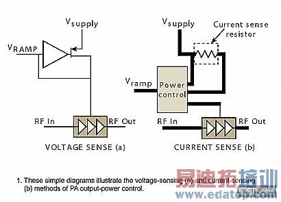
The voltage-sensing (Fig. 1a) and current-sensing (Fig. 1b) methods are often used for PA output-power control. In the voltage-sensing method, a high-speed control loop is incorporated to regulate the collector voltage of the amplifier while the PA stages are held at a constant bias. By regulating the power, the stages are held in saturation across all power levels. As the required output power is decreased from full power down to 0 dBm, the collector voltage is also decreased. The current-sensing method senses the current supplied to the PA through the power supply. A complementary-metal-oxide-semiconductor (CMOS) controller controls the base voltage of the field-effect transistor (FET) with an error voltage generated by applying the ramp voltage, from the DAC, and the current measured to an error amplifier. These are both indirect closed loop methods as there is no direct measurement of the PA''s output power.

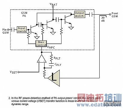
Figure 2 shows a simplified block diagram of a more accurate way to control power by directly detecting the RF power from the amplifier. The module comprises a PA, a silicon power controller, and a number of passive components. The PA output power is controlled by adjusting the bias on the bases of the power transistors. The output power is regulated by a classic automatic-gain-control (AGC) loop. This measures the actual output power of the PA by coupling off a small proportion of the output power using a directional coupler. The sensed power level is applied to a logarithmic amplifier (logamp). The logamp measures the power and compares it to a set point, VSET. If there is a difference between the measured power and the corresponding VSET, an error amplifier adjusts the voltage to the bias controller, VAPC.
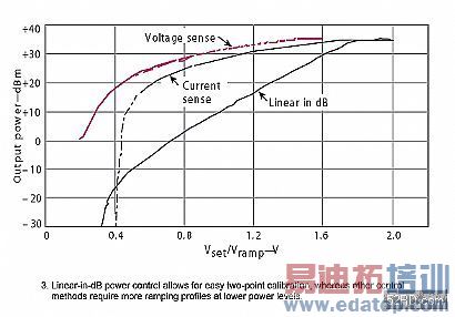
Neither the current-sensing method nor the voltage-sensing technique have any feedback from the output of the PA. Thus, power control is nonlinear in both cases (see Eqs. 1 and 2). The output-power control function in both methods has a nonconstant slope and smaller dynamic range, making ramping to low power levels difficult.


Figure 3 shows that the output power for the RF power-detection method is linear-in-dB over all GSM power levels. This relationship is stable over temperature, and within each frequency band. The part-to-part transfer functions of the DAC that drives the controller, and the logarithmic detector both vary, however, so it is necessary to calibrate the circuit to obtain precise output power. The straightforward linear-in-dB relationship between the output power and VSET, allows for a single two-point calibration in each frequency band. The procedure simply involves applying a VSET that results in an output-power level close to full specified power (e.g., +33 dBm for GSM). Once achieved, the digital-to-analog converter (DAC) code is noted for that power level, which is denoted PHIGH. Then, a VSET is applied that results in an output power close to the minimum output-power level for that standard (e.g., +5 dBm for GSM). Similarly, the DAC code is noted for this power level, which is denoted PLOW. With these four data points, the power output versus VSET can be calculated. This translates into a simple two-point calibration and straight-line approximation.


上一篇:Linear Power Control Of GSM Amplifier Power (2)
下一篇:Make the most of the unlicensed ISM band

