- 易迪拓培训,专注于微波、射频、天线设计工程师的培养
Soft-start enhances LED driver
录入:edatop.com 点击:
To emulate the natural soft start of an incandescent bulb, this circuit makes use of the thermal-foldback protection built into an LED-driver IC (MAX16832). It thereby avoids the annoying and almost instantaneous startup otherwise exhibited by LEDs.
One of the less obvious differences between incandescent light bulbs and LED-based lights is the speed at which they start up. An incandescent bulb requires some time to reach full brightness after you switch it on, and that delay gives the eye a comfortable interval for adjusting to the bright light. LED-based lights lack this property. Instead, their brightness goes from zero to 100% almost instantly. That property is welcome in a camera flash, but rather annoying for general lighting.
Fortunately, you can use the thermal-foldback protection built into an LED-driver IC (MAX16832) to emulate the natural soft start of an incandescent bulb. Figure 1 shows the typical application circuit for this IC.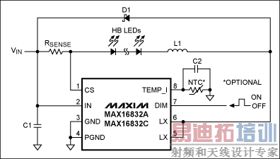
Figure 1. This application circuit is typical for the MAX16832.
A negative-temperature-coefficient resistor (NTC) connected to pin 8 implements the thermal-foldback protection, by reducing output current when the temperature of the LED string exceeds a specified temperature. A constant-current source drives 25µA through this resistor, which is thermally attached to the LEDs. When the resulting NTC voltage drops below 2V (for which RNTC < 80kΩ), an internal comparator alters (lowers) the bandgap reference voltage used by the driver for regulating the LED current. See the LED driver block diagram (Figure 2). The graph on the right in Figure 2 shows this action for a programmed LED current of 666mA. (The RSENSE value is 300mΩ.)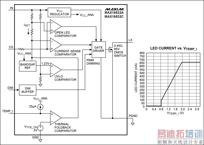
Figure 2. A simplified diagram (left) shows internal operation of the IC in Figure 1. The graph of LED output current versus VTEMP_I (right) assumes RSENSE = 300mΩ. [p]
At start-up, 25µA flows into C2, which charges until its voltage reaches 25µA × RNTC. For an NTC value of 100kΩ and a capacitor value of 10nF, it should reach 2V in less than 2ms. That is, the LED current should ramp from 0mA to 666mA during those two milliseconds. Measurements confirm this assumption: a graph of LED current vs. time (Figure 3) shows that the driver settles to the maximum output current within 2ms.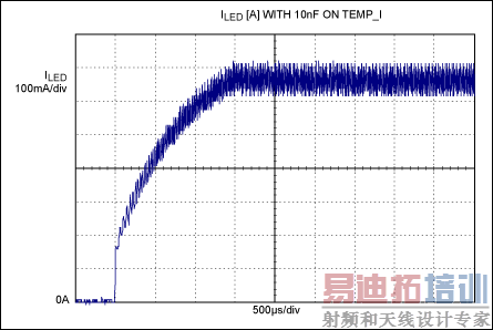
Figure 3. In Figure 1, a graph of LED current vs. startup time with C2 = 10nF shows a soft-start interval of less than two milliseconds.
If you increase the capacitor value by a factor of 100 (to 1µF), the LEDs take about 200ms to reach full power (Figure 4). This timing is visible to the human eye, and gives a welcome sense that the LEDs need to "warm up."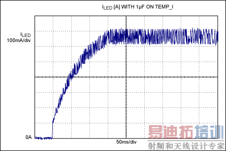
Figure 4. In Figure 1, a graph of LED current vs. startup time with C2 = 1µF shows a soft-start interval of ~200ms.
Using the thermal-foldback circuitry to implement a soft-start for LEDs does not interfere with its protection function. The big capacitor slows that function, but its operation remains satisfactory because thermal effects are inherently slow. Nor is the PWM dimming feature affected. Only the reference voltage is influenced; the rest of the driver behaves normally.
射频工程师养成培训教程套装,助您快速成为一名优秀射频工程师...
天线设计工程师培训课程套装,资深专家授课,让天线设计不再难...
上一篇:LED的实际应用
下一篇:无传感器、无电刷的电动机控制设计实现
射频和天线工程师培训课程详情>>