- 易迪拓培训,专注于微波、射频、天线设计工程师的培养
红外线远程控制电路
红外线远程控制电路 Infa-Red Remote Control
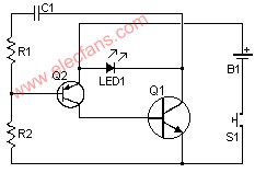
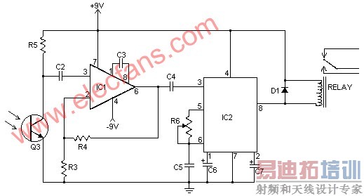
I have received a number of emails requesting schematics for infa-red remotes. So here is one. This remote transmits a tone using an infa-red LED. This tone is decoded by the receiver. Since the receiver only switches when it "hears" the tone, there are no accidental activations.
Schematic For Transmitter


Parts:
Part
Total Qty.
Description
Substitutions
R1
1
22K 1/4W Resistor
R2
1
1 Meg 1/4W Resistor
R3
1
1K 1/4W Resistor
R4, R5
2
100K 1/4W Resistor
R6
1
50K Pot
C1, C2
2
0.01uF 16V Ceramic Disk Capacitor
C3
1
100pF 16V Ceramic Disk Capacitor
C4
1
0.047uF 16V Ceramic Disk Capacitor
C5
1
0.1uF 16V Ceramic Disk Capacitor
C6
1
3.3uF 16V Electrolytic Capacitor
C7
1
1.5uF 16V Electrolytic Capacitor
Q1
1
2N2222 NPN Silicon Transistor
2N3904
Q2
1
2N2907 PNP Silicon Transistor
Q3
1
NPN Phototransistor
D1
1
1N914 Silicon Diode
IC1
1
LM308 Op Amp IC
IC2
1
LM567 Tone Decoder
LED1
1
Infa-Red LED
RELAY
1
6 Volt Relay
S1
1
SPST Push Button Switch
B1
1
3 Volt Battery
Two 1.5V batteries in series
MISC
1
Board, Sockets For ICs, Knob For R6, Battery Holder
RELAY
1
6 Volt Relay
Notes:
1. To adjust the circuit, hold down S1 while pointing LED1 at the receiver. Adjust R6 until you hear the relay click.
2. You can increase range by using a high output LED for LED1.
3. Bright light will stop the receiver from responding to the transmitter.
射频工程师养成培训教程套装,助您快速成为一名优秀射频工程师...
天线设计工程师培训课程套装,资深专家授课,让天线设计不再难...
上一篇:On
Semi
NCP3065
MR16
LED
1-5W驱动解决方案
下一篇:基于Motionchip的直流无刷伺服电机运动控制系统设计和运用

