- 易迪拓培训,专注于微波、射频、天线设计工程师的培养
Connecting dual-digit LED modules
Abstract: The MAX6954/MAX6955 LED display drivers allow users to drive both individual LED digits and shared segment pins. This application note details what steps must be taken to map the digits properly.
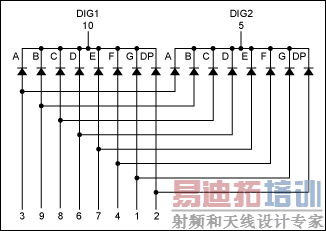
<-- ======================================================================= --><-- CONTENT: DB HTML --><-- ======================================================================= -->Maxim's MAX6954 and MAX6955 LED display drivers can be used to drive LED digits whose segment pins are individually available. The MAX6954/MAX6955 can also be used to drive dual-digit 7-segment LED modules which feature shared segment pins. Figure 1 shows the internal example configuration of such a device.
Figure 1. Internal configuration of a dual-digit LED module.
Up to eight dual-digit modules or 16 digits can be driven by just one MAX6954 or MAX6955. The following module digit-to-digit mapping is recommended to connect these modules to the MAX6954/MAX6955.
Module1-Digit1 -> Digit 0 DIG1 -> CC00 Module1-Digit2 -> Digit 1 DIG2 -> CC01 Module2-Digit1 -> Digit 2 DIG1 -> CC02 Module2-Digit2 -> Digit 3 DIG2 -> CC03 Module3-Digit1 -> Digit 4 DIG1 -> CC04 Module3-Digit2 -> Digit 5 DIG2 -> CC05 Module4-Digit1 -> Digit 6 DIG1 -> CC06 Module4-Digit2 -> Digit 7 DIG2 -> CC07 Module5-Digit1 -> Digit 0a DIG1 -> CC00 Module5-Digit2 -> Digit 1a DIG2 -> CC01 Module6-Digit1 -> Digit 2a DIG1 -> CC02 Module6-Digit2 -> Digit 3a DIG2 -> CC03 Module3-Digit1 -> Digit 4a DIG1 -> CC04 Module3-Digit2 -> Digit 5a DIG2 -> CC05 Module4-Digit1 -> Digit 6a DIG1 -> CC06 Module4-Digit2 -> Digit 7a DIG2 -> CC07
Table 4, Connection Scheme for Sixteen 7-Segment Digits, in the MAX6954/MAX6955 data sheet explains that digit 0, 1, 2, 3, 4, 5, 6, and 7's segment pins are identified by 1a, 1b, 1c, 1d, 1e, 1f, 1g, and 1dp; digit 0a, 1a, 2a, 3a, 4a, 5a, 6a,and 7a's segment pins are identified by 2a, 2b, 2c, 2d, 2e, 2f, 2g, and 2dp.
The scan limit should be set accordingly by writing the proper number to register 0x03. For this example with all eight modules or 16 digits, the scan-limit register should have a content of 0x07. The scan-limit register content can be changed to 0x03 if only four modules or eight digits are driven. When only half of the modules or digits are used, the module digit-to-digit mapping can be changed to the following.
Module1-Digit1 -> Digit 0 DIG1 -> CC00 Module1-Digit2 -> Digit 1 DIG2 -> CC01 Module2-Digit1 -> Digit 2 DIG1 -> CC02 Module2-Digit2 -> Digit 3 DIG2 -> CC03 Module5-Digit1 -> Digit 0a DIG1 -> CC00 Module5-Digit2 -> Digit 1a DIG2 -> CC01 Module6-Digit1 -> Digit 2a DIG1 -> CC02 Module6-Digit2 -> Digit 3a DIG2 -> CC03
射频工程师养成培训教程套装,助您快速成为一名优秀射频工程师...
天线设计工程师培训课程套装,资深专家授课,让天线设计不再难...
上一篇:9个LED组成的音频电平表电路,
Audio
VU
meter
9
leds
下一篇:高清晰LCD
HDTV中使用Cyclone
III
FPGA技术

