- 易迪拓培训,专注于微波、射频、天线设计工程师的培养
Centrifugal fish autofeeder
录入:edatop.com 点击:
This easy as well as cheap but effective device is mainly intended for your ease to leave your fish autofed. You need no longer worry your fish would starve as this autofeeder would replace your job. This autofeeder device will expell pellets by quantity as well as time intervals as you like. Besides, making this circuit seems to be a bit entertaining as you are insisted to make it yourself and so It would develop your creativity. Don’t worry, it works!
This device comprises of 2 sections, electronics and mechanics:
Electronics Section
The main role of this section functions as a timer (few hour intervals) with progress indicator and the mutual action of the relay and capasitor functioning as expelled quantity of pellets. 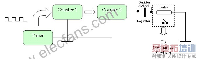
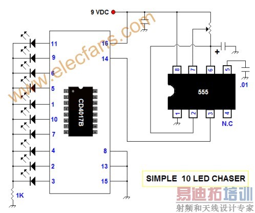
Working System:
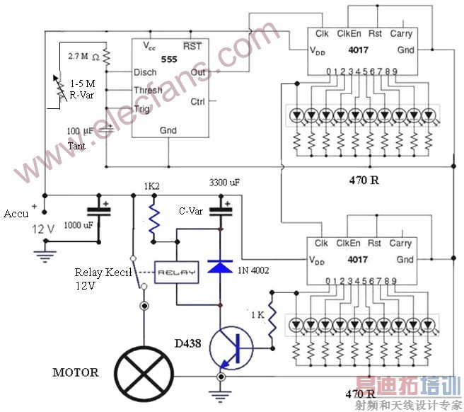
The circuit is using regular timer (IC 555) sending pulse to 2 cascaded counters of CMOS 4017. The output pin from the last counter is then fed to the capacitor and-relay in series. (Remember: a relay owns its own resistance) which consequently trigger the relay for some time to turn on mechanics section. After the capacitor is about to be fully loaded, the relay shuts off. From here we could figure out that the bigger the capacity the longer the relay connects which then causes the motor works to expel pellets centrifugally. The resistor functions to unload the capacitor so that the capacitor is then ready to be loaded for the next cycle.
Time interval if the IC 555 keeps following the formula:
T(555) = 1,1 x R x C
For short, if we set the timer T = 3 minutes, the both counters will multiply the time to be 10 x 10 = 100 times. So the total time intervals would be T = 3 minutes x 10 x 10 = 300 minutes = 5 hours. To change the time intervals simply is by changes/turning R-Var and for the pellet quantity is by changing C-Var size.
Mechanics section
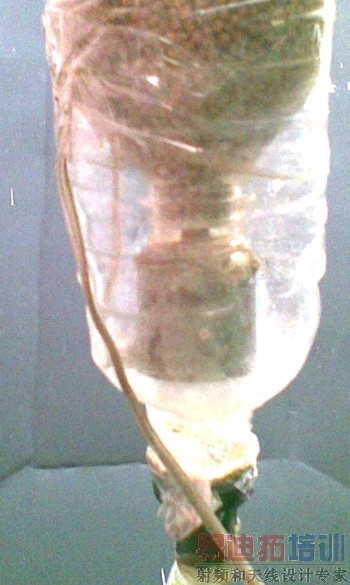
All you need for this section are tape motor 12 V + the ring (plastic or brass), transmission cable, 2 plastic bottle (as shown on the pic), some glue to stick the motor, a coin (about to reach the bottle neck diameter, cutter, match, and solder. For short, try making it yourself following these pics (try to develop yourself about my brief idea):
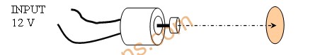
Placement of Coin (plate), ring, and motor stuck together
 [p]
[p]
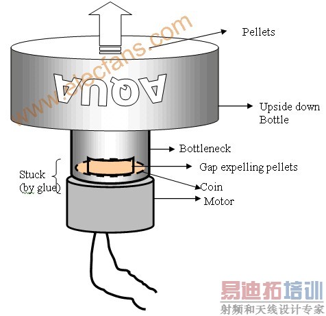
Combination of the both bottleneck and the combined motor
The Mechanics
Well, that’s all. Thank you for your kindly attention, I hope you get profit on it. Good luck.
Reference
The Mechanics
Well, that’s all. Thank you for your kindly attention, I hope you get profit on it. Good luck.
Reference
射频工程师养成培训教程套装,助您快速成为一名优秀射频工程师...
射频和天线工程师培训课程详情>>