- 易迪拓培训,专注于微波、射频、天线设计工程师的培养
powerpcb里面关于max layers的问题


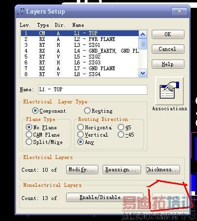
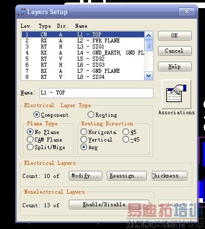
不可以回去了。PADS Layout supports two layer modes, default layer mode and increased layer mode. When a design is in default layer mode, the maximum number of layers is 30. When a design is in increased layer mode, the maximum number of layers is 250. In increased layer mode, the maximum number of electrical layers is 64 and the maximum number of nonelectrical layers is 186.You change from default layer mode to increased layer mode by clicking the Max Layers button in the Layers Setup dialog box. Changing from default layer mode to increased layer mode reassigns all nonelectrical data by increasing all nonelectrical layer numbers by 100. Once you change the design to increased layer mode, you cannot return to default layer mode.
哭!那我该怎么办啊!这次真的完了!
这对设计没什么影响吧,只是你的封装啊什么的别人可能用不了
顶贴排序
我也遇到同样问题,求解!
据说可以改回去,但是要把文件导出为4.0以下格式,在4.0的POWER PCB里编辑即可。我手边没有4.0以下的版本,所以没试过。但看了导出后的asc文件,的确层数已经改回去了。
但是不改回去,元件也是可以使用的。用默认的层的logic原理图,加入相关的元件,然后让logic关联pads,send net list,在pads里出现相关元件,此时pads及元件是default layer mode,把元件保存入库,覆盖掉原来increased layer mode的元件即可。
射频工程师养成培训教程套装,助您快速成为一名优秀射频工程师...
天线设计工程师培训课程套装,资深专家授课,让天线设计不再难...
上一篇:出CAM时出现提示plot is too large for plotting area
下一篇:一些有用的PCB设计文档

