- 易迪拓培训,专注于微波、射频、天线设计工程师的培养
Rayeager PX2-PX2上使用GPIO口的例程
录入:edatop.com 点击:
之前楼主在论坛中已经分享了简单驱动的编写,现在楼主再来教刚接触板子的新手们如何引用调用GPIO,不过这里楼主并没有将GPIO口的函数封装成库,然后在eclipse上调用,楼主这边的例子,只是简单的用adb工具进入板中,然后用一个测试程序使用端口,有兴趣想要在安卓界面调用端口的,可以参考楼主之前写的那编jni调用的帖子。
首先我们依旧来简单地说下步骤,
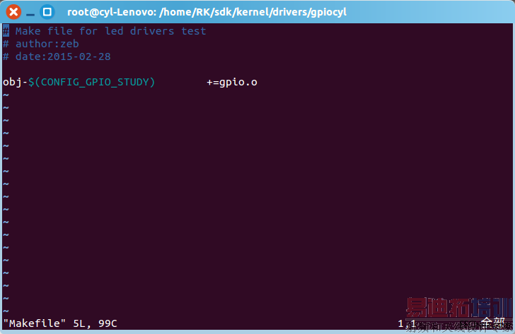
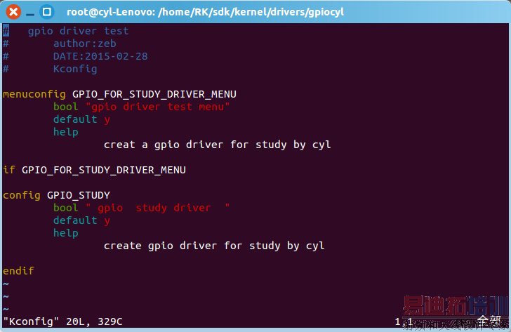
1.在/kernel/drivers下建个文件夹,自己创建并添加Kconfig和makefile,内容如下,
2.在该目录下写个gpio驱动,内容在最后
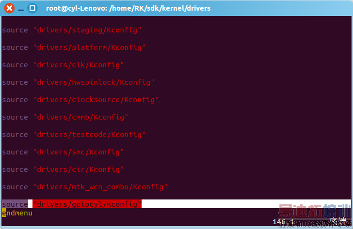
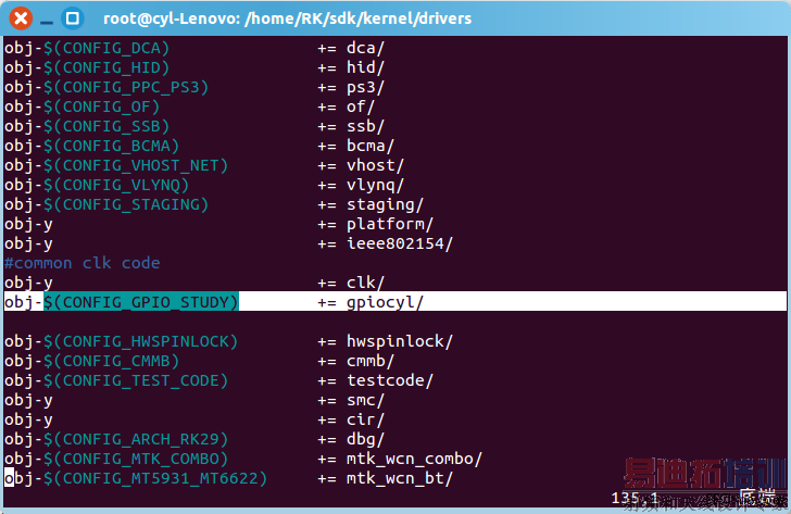
3.返回drivers目录,在目录下修改Kconfig和makefile,修改内容如下
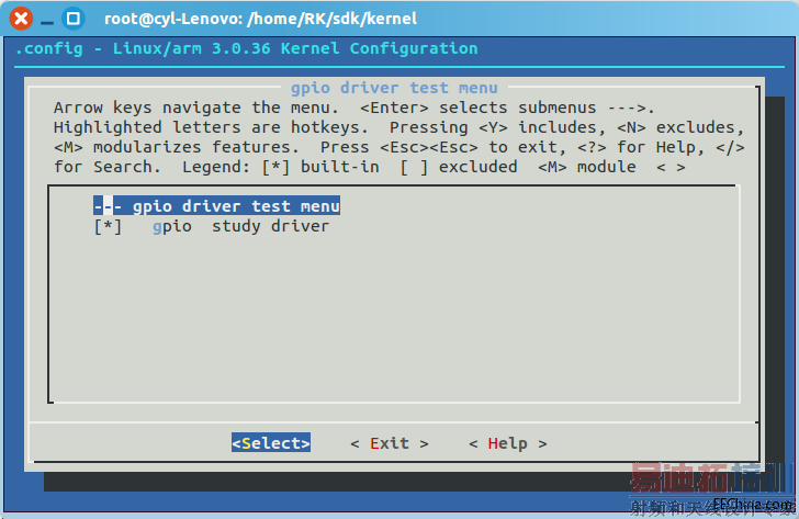
4.进入内核,打开已写好的驱动。
驱动内容如下,
/***********************************************************************************
* driver for GPIO
*
**********************************************************************************/
#include <linux/miscdevice.h>
#include <linux/input.h>
#include <linux/clk.h>
#include <linux/delay.h>
#include <asm/io.h>
#include <asm/uaccess.h>
#include <linux/module.h>
#include <linux/init.h>
#include <mach/gpio.h>
#include <linux/gpio.h>
#define DEVICE_NAME "rkpx2_GPIO" //定义设备名
#define RKPX2_GPIO_MAJOR 101 //定义设备号
static struct class *dev_class//定义设备结构体
static int gpio_open(struct inode *inode, struct file *file)
{
int i
int err
i=0
err = gpio_request(RK30_PIN4_PD1, "GPIO4_D1")//申请端口gpio4_1,成功返回0,失败返回负的错误值
if(err)
{
printk(KERN_ERR "RK_PX2 failed to request GPIO4_D1 n")
return err
}//若申请失败,则报错,然后推出,
err = gpio_request(RK30_PIN4_PD2, "GPIO4_D2")//申请端口gpio4_2,成功返回0,失败返回负的错误值
if(err)
{
printk(KERN_ERR "RK_PX2 failed to request GPIO4_D2 n")
return err
}
err = gpio_request(RK30_PIN4_PD3, "GPIO4_D3")//申请端口gpio4_3,成功返回0,失败返回负的错误值
if(err)
{
printk(KERN_ERR "RK_PX2 failed to request GPIO4_D3 n")
return err
}
err = gpio_request(RK30_PIN4_PD4, "GPIO4_D4")//申请端口gpio4_4,成功返回0,失败返回负的错误值
if(err)
{
printk(KERN_ERR "RK_PX2 failed to request GPIO4_D4 n")
return err
}
printk(KERN_INFO "RK_PX2 GPIO opened 4 !n")
gpio_direction_output(RK30_PIN4_PD1,1)//决定GPIO的方向,为输出
gpio_direction_output(RK30_PIN4_PD2,1)
gpio_direction_output(RK30_PIN4_PD3,1)
gpio_direction_output(RK30_PIN4_PD4,1)
return 0
}
static int gpio_close(struct inode *inode, struct file *file)
{
gpio_free(RK30_PIN4_PD1)
gpio_free(RK30_PIN4_PD2)
gpio_free(RK30_PIN4_PD3)
gpio_free(RK30_PIN4_PD4) //释放端口,
printk(KERN_INFO "RK_PX2 GPIO driver successfully closen")
return 0
}
static int gpio_read(struct file *file, char *buffer, size_t size, loff_t *pos) //从内核中读取GPIO引脚的值
{
int ret
char key_buf[4]
if (gpio_get_value(RK30_PIN4_PD1)==0){
key_buf[0]=0
}else{
key_buf[0]=1
}
if (gpio_get_value(RK30_PIN4_PD2)==0){
key_buf[1]=0
}else{
key_buf[1]=1
}
if (gpio_get_value(RK30_PIN4_PD3)==0){
key_buf[2]=0
}else{
key_buf[2]=1
}
if (gpio_get_value(RK30_PIN4_PD4)==0){
key_buf[3]=0
}else{
key_buf[3]=1
}
ret=copy_to_user(buffer,key_buf,4)//拷贝数据到用户区 ,成功为 0,失败为字节数
return ret
}
static long gpio_ioctl(struct file *file ,unsigned int cmd,unsigned long arg){
switch(cmd){//改变引脚的电平值
case 00: gpio_set_value(RK30_PIN4_PD1,0)
printk("GPIO_D1 is low!n")
break
case 01: gpio_set_value(RK30_PIN4_PD1,1)
printk("GPIO_D1 is high!n")
break
case 10: gpio_set_value(RK30_PIN4_PD2,0)
printk("GPIO_D2 is low!n")
break
case 11: gpio_set_value(RK30_PIN4_PD2,1)
printk("GPIO_D2 is high!n")
break
case 20: gpio_set_value(RK30_PIN4_PD3,0)
printk("GPIO_D3 is low!n")
break
case 21: gpio_set_value(RK30_PIN4_PD3,1)
printk("GPIO_D3 is high!n")
break
case 30: gpio_set_value(RK30_PIN4_PD4,0)
printk("GPIO_D4 is low!n")
break
case 31: gpio_set_value(RK30_PIN4_PD4,1)
printk("GPIO_D4 is high!n")
break
}
return 0
}
/*驱动接口设置*/
static struct file_operations dev_fops = {
.owner = THIS_MODULE,
//.unlocked_ioctl = tq210_gpio_ioctl,
.open = gpio_open,
.release = gpio_close,
.read = gpio_read,
.unlocked_ioctl = gpio_ioctl,
}
/*初始化设备,配置对应的IO,以及注册设备*/
static int __init dev_init(void)
{
int ret
ret=0
ret = register_chrdev(RKPX2_GPIO_MAJOR,"rkpx2_GPIO",&dev_fops)//注册
if (ret<0) {
printk("rkpx2 GPIO for test unable to get major%d n",ret)
return ret
}
dev_class = class_create(THIS_MODULE,"rkpx2_GPIO")//初始化
if (IS_ERR(dev_class)){
unregister_chrdev(RKPX2_GPIO_MAJOR,"rkpx2_GPIO")
return PTR_ERR(dev_class)
}
device_create(dev_class,NULL,MKDEV(RKPX2_GPIO_MAJOR,0),NULL,"rkpx2_GPIO")//创建设备
printk(KERN_INFO "RKPX2 GPIO driver successfully probed!n")
return ret
}
/*注销设备*/
static void __exit dev_exit(void)
{
//misc_deregister(&dev_misc)
gpio_free(RK30_PIN4_PD1)
gpio_free(RK30_PIN4_PD2)
gpio_free(RK30_PIN4_PD3)
gpio_free(RK30_PIN4_PD4)
printk(KERN_INFO "RKPX2 gpio driver successfully exitn")
}
module_init(dev_init)
module_exit(dev_exit)
MODULE_AUTHOR("Rayeager cyl")
MODULE_DESCRIPTION("rkpx2 gpio Driver")
MODULE_LICENSE("GPL")
然后测试程序内容如下:
#include <stdio.h>
#include <stdlib.h>
#include <fcntl.h>
#include <string.h>
#define DEVICE_NAME "/dev/rkpx2_GPIO"
#define LED_OFF 0
#define LED_ON 1
int main(int argc,char **argv){
int fd
int ret
int flag
int pin
int ch
printf("n start test gpio_driversn")
if(strcmp(argv[1],"open")==0){
fd=open(DEVICE_NAME,O_RDWR)
if (fd==-1){
printf("open devices %s errorn",DEVICE_NAME)
}
printf("input the pin you want to operate")
scanf("%d",&pin)
printf("n")
printf("it will be set (1=on or 0=off):")
scanf("%d",&ch)
switch(pin){
case 0: (ch==1 ioctl(fd,1):ioctl(fd,2))break
case 1: (ch==1 ioctl(fd,3):ioctl(fd,4))break
case 2: (ch==1 ioctl(fd,5):ioctl(fd,6))break
case 3: (ch==1 ioctl(fd,7):ioctl(fd,8))break
}
}
if(strcmp(argv[1],"close")==0){
fd=open(DEVICE_NAME,O_RDWR)
close(fd)
}
return 0
}
Android.mk的内容
LOCAL_PATH := $(call my-dir)
include $(CLEAR_VARS)
LOCAL_SRC_FILES:=
test.c
LOCAL_MODULE:=gpioapp
include$(BUILD_EXECUTABLE)
编译测试程序的方法:在源码任意位置建个目录,把Android.mk和测试程序全扔进去,然后执行mm(现在根目录执行source build/envsetup.sh)
实际操作,过程就不说了,亲测可行,正常操作的端口为GPIO4_1234
首先我们依旧来简单地说下步骤,
1.在/kernel/drivers下建个文件夹,自己创建并添加Kconfig和makefile,内容如下,
2.在该目录下写个gpio驱动,内容在最后
3.返回drivers目录,在目录下修改Kconfig和makefile,修改内容如下
4.进入内核,打开已写好的驱动。
驱动内容如下,
/***********************************************************************************
* driver for GPIO
*
**********************************************************************************/
#include <linux/miscdevice.h>
#include <linux/input.h>
#include <linux/clk.h>
#include <linux/delay.h>
#include <asm/io.h>
#include <asm/uaccess.h>
#include <linux/module.h>
#include <linux/init.h>
#include <mach/gpio.h>
#include <linux/gpio.h>
#define DEVICE_NAME "rkpx2_GPIO" //定义设备名
#define RKPX2_GPIO_MAJOR 101 //定义设备号
static struct class *dev_class//定义设备结构体
static int gpio_open(struct inode *inode, struct file *file)
{
int i
int err
i=0
err = gpio_request(RK30_PIN4_PD1, "GPIO4_D1")//申请端口gpio4_1,成功返回0,失败返回负的错误值
if(err)
{
printk(KERN_ERR "RK_PX2 failed to request GPIO4_D1 n")
return err
}//若申请失败,则报错,然后推出,
err = gpio_request(RK30_PIN4_PD2, "GPIO4_D2")//申请端口gpio4_2,成功返回0,失败返回负的错误值
if(err)
{
printk(KERN_ERR "RK_PX2 failed to request GPIO4_D2 n")
return err
}
err = gpio_request(RK30_PIN4_PD3, "GPIO4_D3")//申请端口gpio4_3,成功返回0,失败返回负的错误值
if(err)
{
printk(KERN_ERR "RK_PX2 failed to request GPIO4_D3 n")
return err
}
err = gpio_request(RK30_PIN4_PD4, "GPIO4_D4")//申请端口gpio4_4,成功返回0,失败返回负的错误值
if(err)
{
printk(KERN_ERR "RK_PX2 failed to request GPIO4_D4 n")
return err
}
printk(KERN_INFO "RK_PX2 GPIO opened 4 !n")
gpio_direction_output(RK30_PIN4_PD1,1)//决定GPIO的方向,为输出
gpio_direction_output(RK30_PIN4_PD2,1)
gpio_direction_output(RK30_PIN4_PD3,1)
gpio_direction_output(RK30_PIN4_PD4,1)
return 0
}
static int gpio_close(struct inode *inode, struct file *file)
{
gpio_free(RK30_PIN4_PD1)
gpio_free(RK30_PIN4_PD2)
gpio_free(RK30_PIN4_PD3)
gpio_free(RK30_PIN4_PD4) //释放端口,
printk(KERN_INFO "RK_PX2 GPIO driver successfully closen")
return 0
}
static int gpio_read(struct file *file, char *buffer, size_t size, loff_t *pos) //从内核中读取GPIO引脚的值
{
int ret
char key_buf[4]
if (gpio_get_value(RK30_PIN4_PD1)==0){
key_buf[0]=0
}else{
key_buf[0]=1
}
if (gpio_get_value(RK30_PIN4_PD2)==0){
key_buf[1]=0
}else{
key_buf[1]=1
}
if (gpio_get_value(RK30_PIN4_PD3)==0){
key_buf[2]=0
}else{
key_buf[2]=1
}
if (gpio_get_value(RK30_PIN4_PD4)==0){
key_buf[3]=0
}else{
key_buf[3]=1
}
ret=copy_to_user(buffer,key_buf,4)//拷贝数据到用户区 ,成功为 0,失败为字节数
return ret
}
static long gpio_ioctl(struct file *file ,unsigned int cmd,unsigned long arg){
switch(cmd){//改变引脚的电平值
case 00: gpio_set_value(RK30_PIN4_PD1,0)
printk("GPIO_D1 is low!n")
break
case 01: gpio_set_value(RK30_PIN4_PD1,1)
printk("GPIO_D1 is high!n")
break
case 10: gpio_set_value(RK30_PIN4_PD2,0)
printk("GPIO_D2 is low!n")
break
case 11: gpio_set_value(RK30_PIN4_PD2,1)
printk("GPIO_D2 is high!n")
break
case 20: gpio_set_value(RK30_PIN4_PD3,0)
printk("GPIO_D3 is low!n")
break
case 21: gpio_set_value(RK30_PIN4_PD3,1)
printk("GPIO_D3 is high!n")
break
case 30: gpio_set_value(RK30_PIN4_PD4,0)
printk("GPIO_D4 is low!n")
break
case 31: gpio_set_value(RK30_PIN4_PD4,1)
printk("GPIO_D4 is high!n")
break
}
return 0
}
/*驱动接口设置*/
static struct file_operations dev_fops = {
.owner = THIS_MODULE,
//.unlocked_ioctl = tq210_gpio_ioctl,
.open = gpio_open,
.release = gpio_close,
.read = gpio_read,
.unlocked_ioctl = gpio_ioctl,
}
/*初始化设备,配置对应的IO,以及注册设备*/
static int __init dev_init(void)
{
int ret
ret=0
ret = register_chrdev(RKPX2_GPIO_MAJOR,"rkpx2_GPIO",&dev_fops)//注册
if (ret<0) {
printk("rkpx2 GPIO for test unable to get major%d n",ret)
return ret
}
dev_class = class_create(THIS_MODULE,"rkpx2_GPIO")//初始化
if (IS_ERR(dev_class)){
unregister_chrdev(RKPX2_GPIO_MAJOR,"rkpx2_GPIO")
return PTR_ERR(dev_class)
}
device_create(dev_class,NULL,MKDEV(RKPX2_GPIO_MAJOR,0),NULL,"rkpx2_GPIO")//创建设备
printk(KERN_INFO "RKPX2 GPIO driver successfully probed!n")
return ret
}
/*注销设备*/
static void __exit dev_exit(void)
{
//misc_deregister(&dev_misc)
gpio_free(RK30_PIN4_PD1)
gpio_free(RK30_PIN4_PD2)
gpio_free(RK30_PIN4_PD3)
gpio_free(RK30_PIN4_PD4)
printk(KERN_INFO "RKPX2 gpio driver successfully exitn")
}
module_init(dev_init)
module_exit(dev_exit)
MODULE_AUTHOR("Rayeager cyl")
MODULE_DESCRIPTION("rkpx2 gpio Driver")
MODULE_LICENSE("GPL")
然后测试程序内容如下:
#include <stdio.h>
#include <stdlib.h>
#include <fcntl.h>
#include <string.h>
#define DEVICE_NAME "/dev/rkpx2_GPIO"
#define LED_OFF 0
#define LED_ON 1
int main(int argc,char **argv){
int fd
int ret
int flag
int pin
int ch
printf("n start test gpio_driversn")
if(strcmp(argv[1],"open")==0){
fd=open(DEVICE_NAME,O_RDWR)
if (fd==-1){
printf("open devices %s errorn",DEVICE_NAME)
}
printf("input the pin you want to operate")
scanf("%d",&pin)
printf("n")
printf("it will be set (1=on or 0=off):")
scanf("%d",&ch)
switch(pin){
case 0: (ch==1 ioctl(fd,1):ioctl(fd,2))break
case 1: (ch==1 ioctl(fd,3):ioctl(fd,4))break
case 2: (ch==1 ioctl(fd,5):ioctl(fd,6))break
case 3: (ch==1 ioctl(fd,7):ioctl(fd,8))break
}
}
if(strcmp(argv[1],"close")==0){
fd=open(DEVICE_NAME,O_RDWR)
close(fd)
}
return 0
}
Android.mk的内容
LOCAL_PATH := $(call my-dir)
include $(CLEAR_VARS)
LOCAL_SRC_FILES:=
test.c
LOCAL_MODULE:=gpioapp
include$(BUILD_EXECUTABLE)
编译测试程序的方法:在源码任意位置建个目录,把Android.mk和测试程序全扔进去,然后执行mm(现在根目录执行source build/envsetup.sh)
实际操作,过程就不说了,亲测可行,正常操作的端口为GPIO4_1234
射频工程师养成培训教程套装,助您快速成为一名优秀射频工程师...
射频和天线工程师培训课程详情>>