- 易迪拓培训,专注于微波、射频、天线设计工程师的培养
13.56 MHz power amp, antenna and buffer design
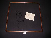
www.nxp.com/documents/data_sheet/MFRC531.pdf).I have made the antenna from the TI cookbook (
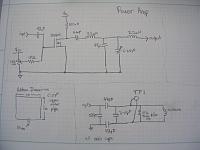
http://www.ti.com/rfid/docs/manuals/...naCookbook.pdf).It is the 1m x 1m antenna for which I will attach the dimensions.I am using a power amp design found in a previous experiment located on pg 7 of (eprint.iacr.org/2006/054.pdf).My design is a bit different and the schematic is included in the attachment.
I have not been able to the the signal large enough across the antenna.I measured from TP1 on the attached schematic and the most I have gotten was 60Vpp.I believe that I should get alot more.The impedence from the antenna is about 70 ohms and it is designed for 50 so I am wondering if that is a problem?
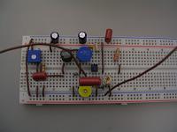
I have built a recieve circuit using a J310 chip (
Digi-Key - J310-ND (Manufacturer - J310)) but was not able to get a signal back.
I am wondering if it is possible to power an antenna that size, will an antenna that size pick up the signal from a passive credit card tag and where should I attempt to retrieve the signal from?
Please as questions if things are not clear.
Your help is much appreciated.
Kevin Weiss


Of course the impedance of antenna and circuits should be matched.
And the signal is 13.56MHz, so the lamda is 22.1m, it seems your antenna is mall and the distance (1M) is in the near field. Do you simulate the EM field strength?
There are two points involved with your project.
- achieving the minimum required field strength at the tag location. I would calculate ISO 14443 specified 1.5 A/m as a first guess. Probably a value between 0.5 and 1 A/m can be sufficient.
- receiving the tag signal
Did you calculate the loop voltage required for 1 A/m in 1 m distance. It's several kV.
申明:网友回复良莠不齐,仅供参考。如需专业学习,请查看13.56MHz NFC/RFID天线设计培训课程。
上一篇:13.56和900mhz电子标签天线设计咨询
下一篇:UHF陶瓷标签天线模型问题?


