- 易迪拓培训,专注于微波、射频、天线设计工程师的培养
RF SWITCH in 13.56MHZ
GaAs SP4T High Power Switch
DC - 3 GHz
MASW-007813
M/A-COM Inc. and its affiliates reserve the right to make changes to the
product(s) or information contained herein without notice. M/A-COM makes
no warranty, representation or guarantee regarding the suitability of its
products for any particular purpose, nor does M/A-COM assume any liability
whatsoever arising out of the use or application of any product(s) or
information.
? North America Tel: 800.366.2266 / Fax: 978.366.2266
? Europe Tel: 44.1908.574.200 / Fax: 44.1908.574.300
? Asia/Pacific Tel: 81.44.844.8296 / Fax: 81.44.844.8298
RoHS
Compliant
Features
? Low Voltage Operation: 2.5 V
? Low Harmonics:50 MHz dBm — 96 —
IP3 Two Tone, +26 dBm/Tone, 5 MHz spacing, > 50 MHz dBm — 58 —
2nd Harmonic 1 GHz, Pin = +34 dBm dBc — -76 -68
3. For positive voltage control, external DC blocking capacitors are required on all RF ports.
4. Insertion loss can be optimized by varying the DC blocking capacitor value, e.g. 1000 pF for 100 MHz - 1 GHz, 39 pF for 0.5 GHz - 3 GHz.
V1 V2 V3 V4 ANT12 3 4
10 0 0On OffOffOff
01 0 0Off OnOffOff
00 1 0Off OffOnOff
0 0 0 1Off OffOffOn
Truth Table 5,6
5. Differential voltage, V (state 1) - V (state 0), must be +2.5 V
minimum and must not exceed 8.5 V.
6. 0 = -8.5 V to 0 V, 1 = -6 V to 8.5 V
Parameter Absolute Maximum
Max Input Power
(0.5 - 3 GHz, 2.75 V Control) +38 dBm
Operating Voltage +8.5 volts
Operating Temperature -40°C to +85°C
Storage Temperature -65°C to +150°C
Rather than posting verbose technical data, you may want to tell a word about the antenna impedance and expected power level of the 13.56 MHz transmitter.
hi,FvM,thanks for your reply,my antenna impandance is 50 ohm,and power level is 35dBm,it's ok used masw-007813 in 915mhz reader ,but in 13.56mhz reader is not good.miss matching?this frequency seem don't care strictly.
Two remarks.
- You are operating the switch rather near to maximum ratings. I'm not sure if you can guarantee to keep it in case of possible antenna mismatch. Consider, that the critical parameter for the device is most likely maximum voltage.
- I assume, that you scaled the necessary decoupling capacitors at the switch ports according to your operating frequency. I would use at least several nF.
Apart from these points, the switch should perfectly work at low frequency.
hi,FvM,i used 0.1uF decoupling capacitor at the swtich output ports,is it bigger? the switch max input power is 38dBm,35 should be ok.
FvM,I tried to change decoupling capacitor from 4.7nF to 0.1uF,but the problem is still,and i found a strange thing:when i read card on the antenna of passed port,its effect is very bad,just only 10cm range,but the read range of other isolated ports is all the better,i measured spectrum each port,the passed port's is disorder but other ports is normal.
As you see from the M/A-Com datasheet graphs there are no specifications below 50MHz.
Take a look to their competitor, which is more realistic.
http://www.skyworksinc.com/products.aspx?CategoryID=89
vfone,i looked over the datasheet that you commended,but the max powercan't meet my need. my reader output 35dBm,i need to find out the reason of current board,why it is no normal connected switch module,but very good disconnect it,why each outputof switch have enough power in 13.56Mhz,used in 915Mhz is ok. very perplexing!
As you see from the M/A-Com datasheet graphs there are no specifications below 50MHz No, the datasheet's insertion loss specification is even including DC (obviously ignoring the coupling capacitors).
and i found a strange thing:when i read card on the antenna of passed port,its effect is very bad,just only 10cm range,but the read range of other isolated ports is all the better,i measured spectrum each port,the passed port's is disorder but other ports is normal. Can't give a meaningful explanation from the distance. Sounds like a basic problem, e.g. incorrect control voltage level or defective chip. You should verify the switch operation by signal generator/level measurement first. I can hardly imagine, that the problem is related to signal frequency.
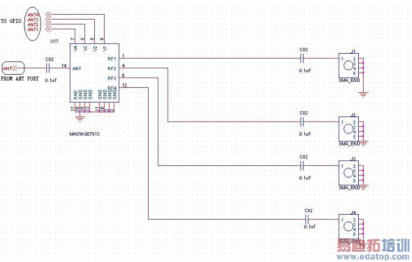
FvM,thanks a lot! i verify control voltage is ok,according to the datasheet,max control voltage is 8.5V,i use 3.3v from GPIO of MCU,chip is also no problem,because i use the same switch chipthat in 915Mhz transmitter,just change DC bloking capacitor from 68pF to 0.1uF,attached antenna switch file,pls help me to check the reason,thank you!
Make RF measurements.
申明:网友回复良莠不齐,仅供参考。如需专业学习,请查看13.56MHz NFC/RFID天线设计培训课程。


