- 易迪拓培训,专注于微波、射频、天线设计工程师的培养
Problem in calculation inductance from Sp simulation - ADS
I am simulating the inductance and coupling coefficient of transformer using ADS. My procedure consists of three steps. First, I create a transformer using CoilSys in ADS and then simulate its S-parameter, then I separate this transformer into two inductors and simulate their S-parameter. After that, based on S-parameter I calculate the inductance of two inductors in two cases: (1) transformer (2) two separated inductors then I use the T-model of transformer to determine the mutual inductance and coupling coefficient.
Theoretically, inductance of inductor is determined using the equation:
L = imag(Z_ind)/(omega)
I found that the S11 = (Zin-Z0)/(Zin+Z0) => Zin = Z0*(1+S11)/(1-S11) when the other ports are matched. Furthermore, the Zin of the two-port inductor = Z0 + Z_ind, so we can find the Z_ind of inductor using S-parameter and then calculate the inductance using the previous equation.
However, I have read in one ADS application note that there are equations to determine the inductance of inductor
(http://muehlhaus.com/support/ads-app...nctions-in-ads)
They said that we can use stoz function to translate the S-parameter to Z-parameter and then thank to the equation: Zseries = (Z11*Z22 - Z12*Z21)/Z21, they use this impedance to calculate the inductance.
I have a question that does the Z11 from stoz() function different from the Zin, which is calculated from S11 and another question is what Zseries means and why do we use this impedance to calculate the inductance. I found that the inductance, calculated from Zseries and Zin are quite similar, and these results are more different from the inductance, determined from Z11_stoz.
Would you please advise me or give me some documents to solve this problem.
Thank you very much.
You quoted my appnote, so let me try to explain the different concepts.
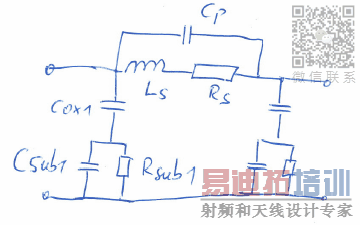
Let's start with inductance. Below is the simplified equivalent circuit model for on inductor in Silicon technology. When we want to extract inductance, we need to define what inductance value we mean: the core Ls value? The effective value with parasitics? For what port connection, because that gives different effective values?
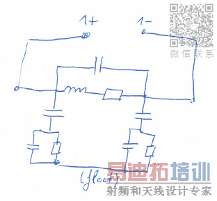
If we are a PDK modelling engineer, we might want the core Ls value (excluding paraitics). For circuit design, we are more interested in an effective series inductance value that includes all the effects (includes parasitics). In Silicon technologies, inductors in tank circuit are usually driven in differential mode, so we want the effective value for this configuration between 1+ and 1- :
The equation from my appnote converts the 2-port parameters (one port on each end of the inductor) into 1-port parameter measured between the two terminals. The result for inductance is the same as directly simulating as a 1-port, and then using L = imag(Z_ind)/(omega). However, the advantage of using 2-port EM data in circuit simulation is that it is valid both differential and common mode excitation (and a mixture of both). That's why I prefer simulating as a 2-port (data for circuit sim), and instead of doing another 1-port sim for plotting differential inductor parameters that is calculated by Zseries = (Z11*Z22 - Z12*Z21)/Z21
As explained above, the circuit use in Si technology is differential drive of the inductor. If you measured into port 1, with port 2 terminated into 50 Ohm, the effect of parasitics is different. That is why evaluting inductor parameters should be done for the actual model of operation, i.e. differentially between the inductor terminals for differential circuit use.
Hope this makes sense now?
Best regards
Volker
Dear Volker,
Thank you very much for your help. Your app notes are very helpful.
Best Regards,
irisaru
申明:网友回复良莠不齐,仅供参考。如需专业帮助,请学习易迪拓培训专家讲授的ADS视频培训课程。
上一篇:ADS EM simulation: where should I place ports?
下一篇:How to model absorbing material in ADS Momentum (reflectivity of 20 dB or more)?
 国内最全面、最专业的Agilent ADS培训课程,可以帮助您从零开始,全面系统学习ADS设计应用【More..】
- Agilent ADS教学培训课程套装
- 两周学会ADS2011、ADS2013视频教程
- ADS2012、ADS2013射频电路设计详解
- ADS高低阻抗线微带滤波器设计培训教程
- ADS混频器仿真分析实例视频培训课程
- ADS Momentum电磁仿真设计视频课程
- ADS射频电路与通信系统设计高级培训
- ADS Layout和电磁仿真设计培训视频
- ADS Workspace and Simulators Training Course
- ADS Circuit Simulation Training Course
- ADS Layout and EM Simulation Training Course
- Agilent ADS 内部原版培训教材合集


