- 易迪拓培训,专注于微波、射频、天线设计工程师的培养
how design CPw with strips in ADS?
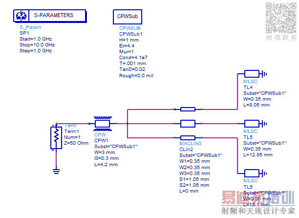
I was drawn below figure in ADS, but i dont know why this circuit has error on MACLIN block?!
it is a cpw feed line with 3ple strips.
the strips connect to CPW with MACLIN because the space between strips are important, but this circuit cannot be run in ADS.
Can you help me?

MACLIN3 is a microstrip model and needs an MSUB block (not CPWSUB).
Is there any similar block like MACLINE3 for cpw structures?
how can i change my structure?
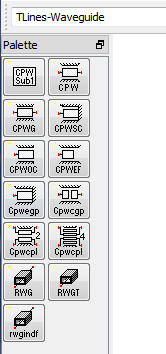
There are only few waveguide schematic models.

I think your approach might be wrong.
What are you trying to model/layout?
Do you have an EM simulator available (Momentum, Sonnet etc.)?
I want to model three straight strip that connected to the cpw feed on one layer. The figure like below. I cant get the answer yet. this circuit works in triple frequency. i was modeled it at HFSS and got the result.
Hmmm ... there are certainly no circuit models to simulate this properly. You have to model this with an EM simulator.
Personally, I would not use HFSS for this planar work, but that's your choice.
If this is not GCPW, i.e. no other ground below, what is it? Antenna?
which package do you mean as EM simulator?
yes, it is antenna, and work at 3ple frequencies, a single strip at cpw between two others is main feed and two other strips in cpw used at ground. the straight strips are equal to lambda/4 and work at certain frequency
do you have any idea to model it on ADS?
It depends if you want to include the "edge of the substrate" effect, i.e. finite substrate size.
Maybe it is good enough to simulate with infinite substrate size -> planar simulator like Momentum.
Forget about the circuit models. Draw the structure in layout, then simulate with Momentum.
It is good idea, but I think if i can draw in layout it means i can plot design model!
i dont draw before in layout, doesnt layout need MACLINE?
just like a photo that i uploaded i draw some strips?
how define CPW?
---------- Post added at 18:06 ---------- Previous post was at 18:05 ----------
i was heard before, we can export from layout to circuit model, is it true? and how can i do this?
You do not need auto-generated layout!
You can simply draw polygons in layout, and then do EM analysis with Momentum.
Before you start, look at the Momentum CPW examples. For CPW, Momentum uses a special port type where you draw (and mesh) the slots instead of the mesh. But I am not a Momentum user, so I can not help you with the details.
This is true if you place transmission line models in layout, instead of simple polygons.
This does not work for your layout, because there are no circuit models. You need to draw with simple polygons and then use Momentum.
thanks, i will try it
申明:网友回复良莠不齐,仅供参考。如需专业帮助,请学习易迪拓培训专家讲授的ADS视频培训课程。
上一篇:Issue with consistency in ADS-EMDS co-simulation results
下一篇:set up optimization in ads
 国内最全面、最专业的Agilent ADS培训课程,可以帮助您从零开始,全面系统学习ADS设计应用【More..】
- Agilent ADS教学培训课程套装
- 两周学会ADS2011、ADS2013视频教程
- ADS2012、ADS2013射频电路设计详解
- ADS高低阻抗线微带滤波器设计培训教程
- ADS混频器仿真分析实例视频培训课程
- ADS Momentum电磁仿真设计视频课程
- ADS射频电路与通信系统设计高级培训
- ADS Layout和电磁仿真设计培训视频
- ADS Workspace and Simulators Training Course
- ADS Circuit Simulation Training Course
- ADS Layout and EM Simulation Training Course
- Agilent ADS 内部原版培训教材合集
