- 易迪拓培训,专注于微波、射频、天线设计工程师的培养
[ADS] S-parameters plot in ADS via S1p file?
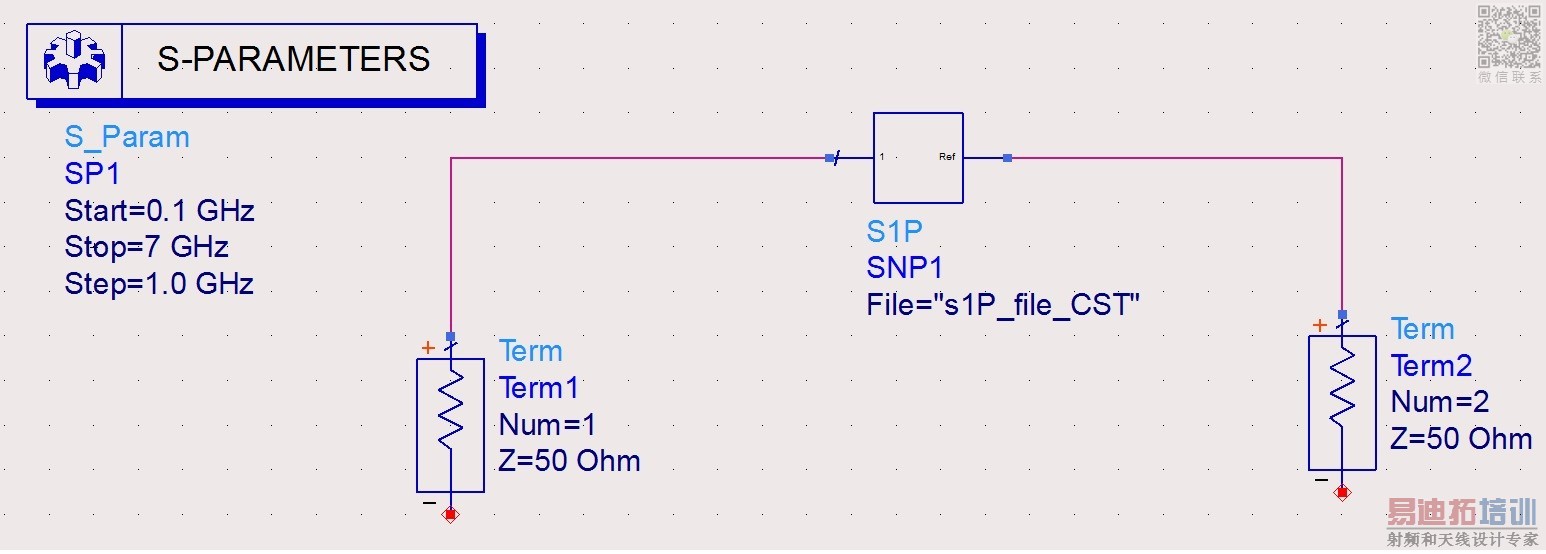
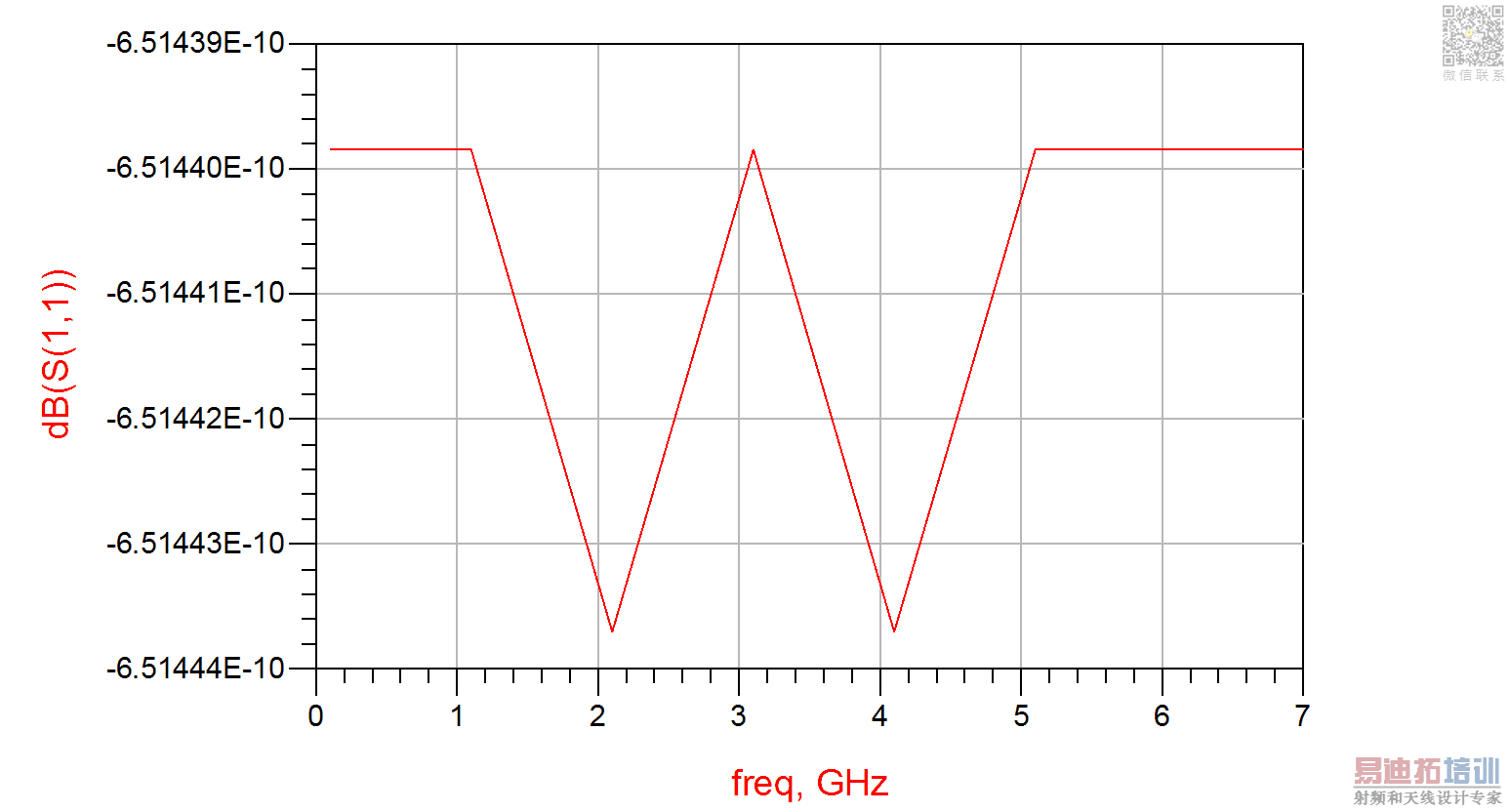
I am unable to generate the required s-parameters results.
Can someone please let me know if I am doing anything wrong here.
It will work much better if you connect ground elements at both Term (-) terminals
In addition to the missing ground, as Volker mentions, if the s-parameter file you are using is 1 port data (S1P) then you should not be performing a two port simulation. You only need one Term, connected to pin 1 of the S1P element. The other pin on the S1P is the reference pin and that should be grounded. Then the S11 measurement should reflect the data in the file.
Thankyou @volker and @Real, for the quick response.
The results generated are now somewhat acceptable.
It should be like fig 1 but Im getting results like fig 2...Any ideas?
Fig.1 [CST S-parameters]
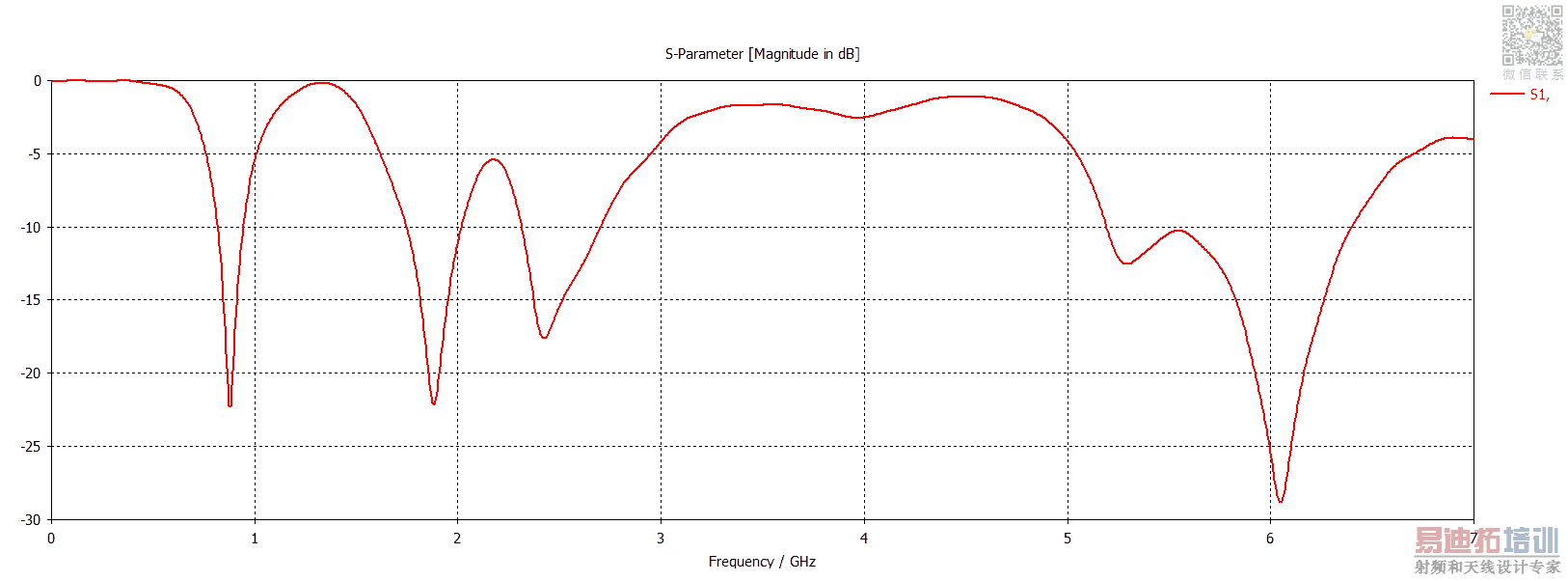
Fig.2 [ADS s-parameters]
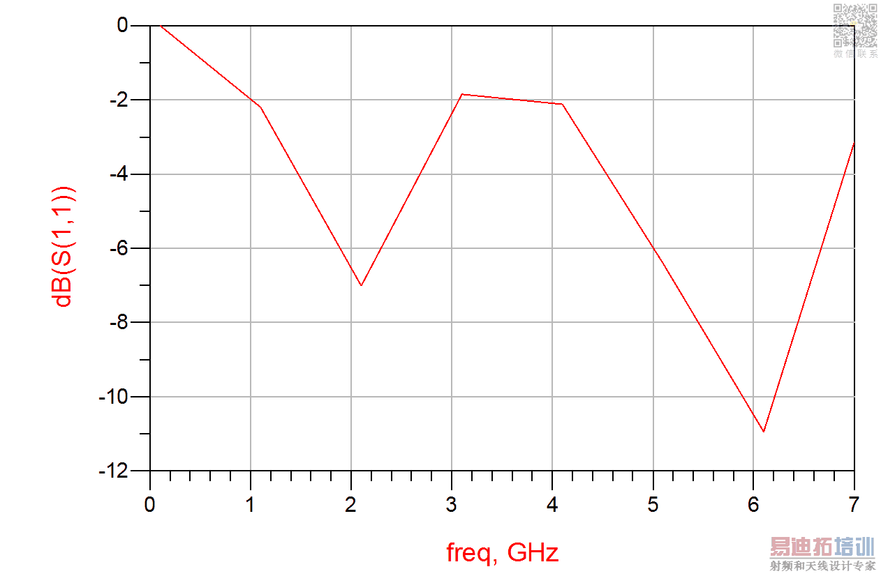
Sure, you have defined frequency step 1GHz in the sweep definition ... and this is what you get, 1GHz steps.
@volker..Thnx..
I adjusted the Number of points as per my frequ and now I am getting the correct results.
One more questions about introducing coupler into the same design..
I would like to know the effect of s1p file when passed thorough a 3dB coupler working at 925 MHz frequency.
The circuit is shown below with relevant results...Is the structure correct?
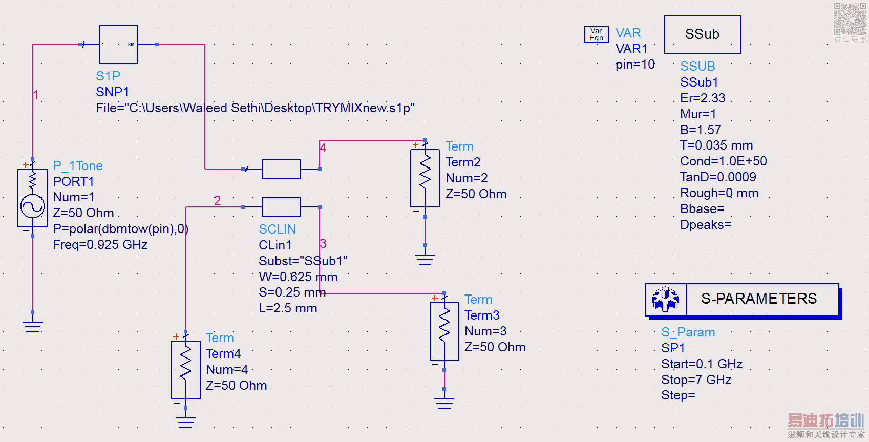
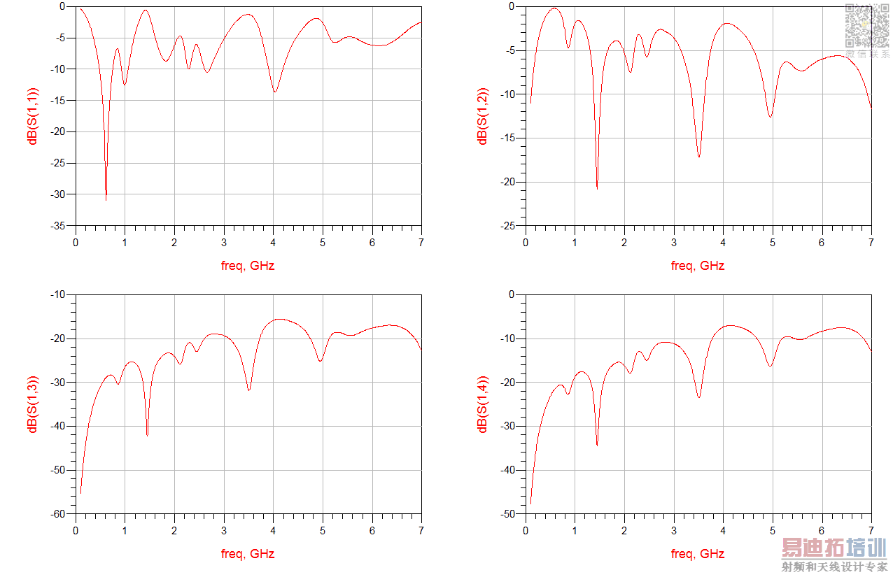
No, this setup is wrong.
You need to use the S1P file as a termination (gnd node connected to gnd), not as a series element. This means your testbench will have only 3 ports: source port, reflection port and isolation port.
Thankyou for the correction.
I am following a paper where they have used a 3 pin coupler with a power source and a s1p file. The Connections of coupler to/from are described as following;
" Pin 3 of coupler is attached to the one pin of s1p, another pin of s1p is grounded. Pin 1 of coupler is connected to a port (P_1Tone). Pin 2 of coupler is connected to impedance match network".
From the above description I have made the following ADS circuit having results as shown. AM I correct with this design? i mean what about the 4-pin?Does ADS has a 3 pin coupler or I need to make one?
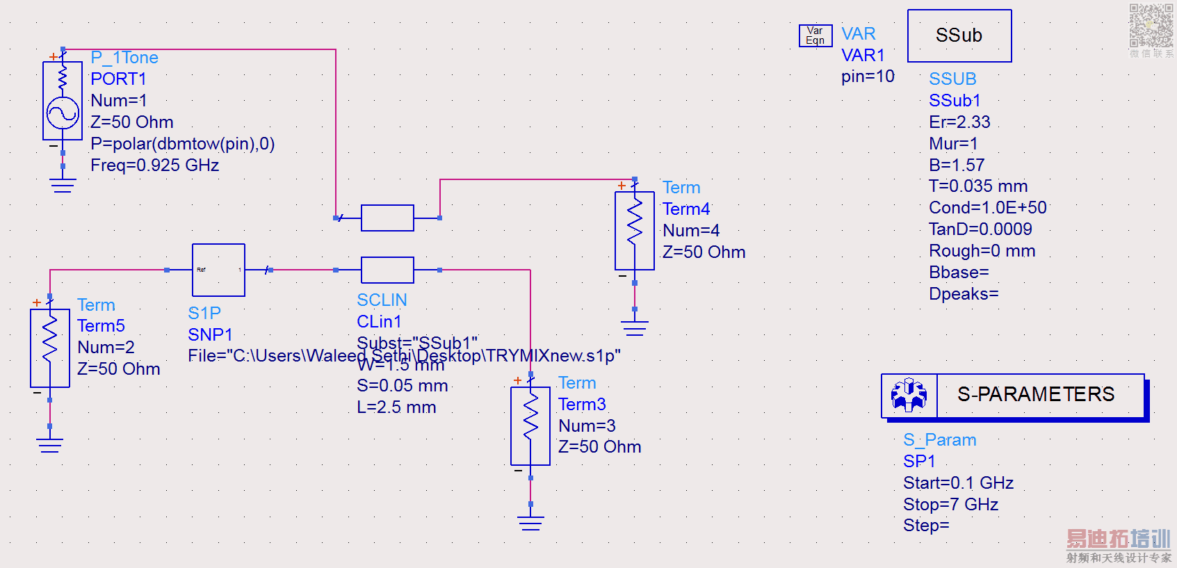
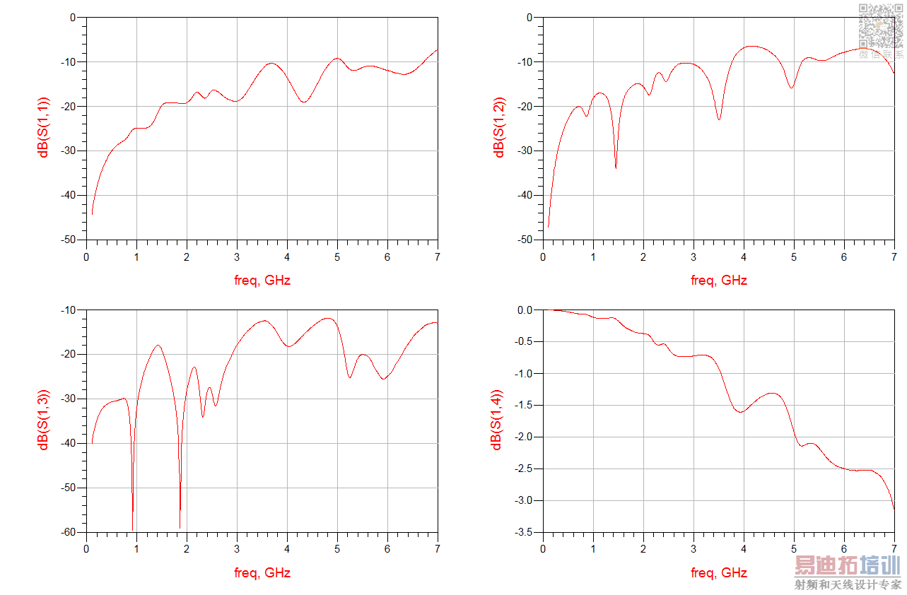
No, again this is not correct.
You can never have a Term on the reference pin of the S1P element. It should always be grounded in this sort of application. An S1P data file represents one port data. It is a measure of the impedance or reflection coefficient, however you can think of it most easily, of a complete circuit, including any termination connected to it at the remote end of the circuit, as presented at that single input/output pin. It can never be treated as a through connection, only a load or termination as stated by Volker above. Even the circuit you describe states that "another pin of s1p is grounded" so that is what you should do.
Ok. Thank you for the clarification. I redid the design as shown below. Hopefully its correct this time. Are the results OK? for 925 MHz
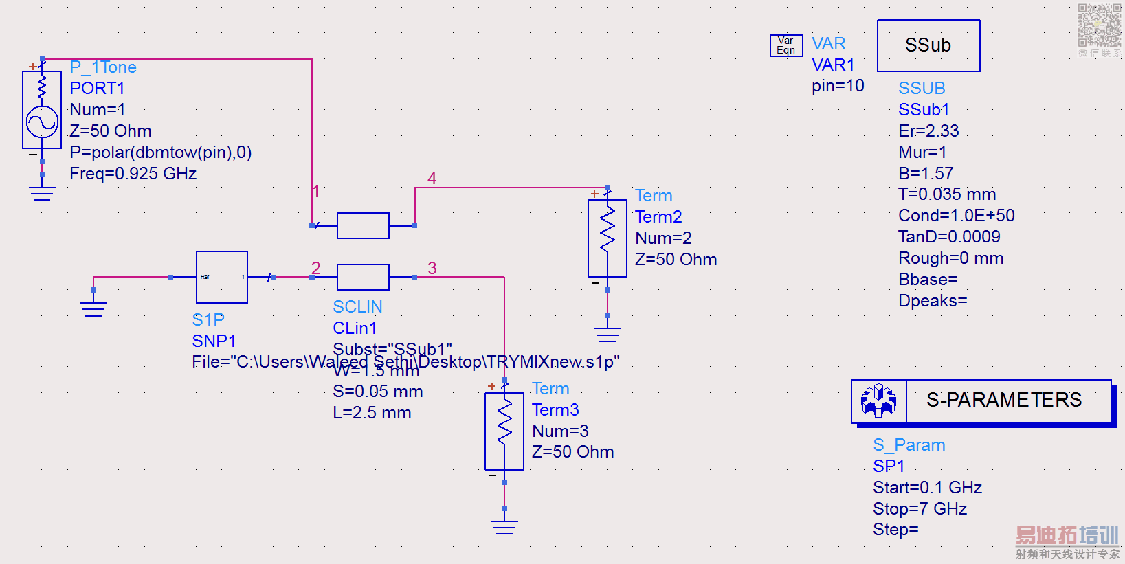
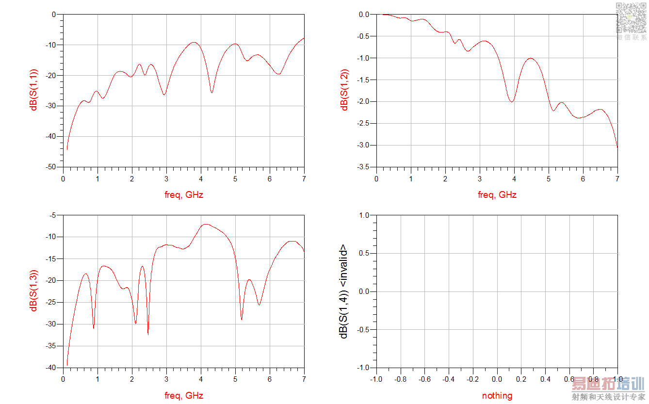
It depends what you try to do with the coupler. At the moment, most of the power goes to your port 2 and not the the antenna.
http://www.microwaves101.com/encyclo...-line-couplers
I think you want to connect the antenna at the "thru" port of the coupler. Swap port 2 and the antenna.
申明:网友回复良莠不齐,仅供参考。如需专业帮助,请学习易迪拓培训专家讲授的ADS视频培训课程。
上一篇:ADS Momentum simulation of the patch antenna with partial ground
下一篇:Re: Agilent ADS Momentum crashes with strange errors
 国内最全面、最专业的Agilent ADS培训课程,可以帮助您从零开始,全面系统学习ADS设计应用【More..】
- Agilent ADS教学培训课程套装
- 两周学会ADS2011、ADS2013视频教程
- ADS2012、ADS2013射频电路设计详解
- ADS高低阻抗线微带滤波器设计培训教程
- ADS混频器仿真分析实例视频培训课程
- ADS Momentum电磁仿真设计视频课程
- ADS射频电路与通信系统设计高级培训
- ADS Layout和电磁仿真设计培训视频
- ADS Workspace and Simulators Training Course
- ADS Circuit Simulation Training Course
- ADS Layout and EM Simulation Training Course
- Agilent ADS 内部原版培训教材合集
