- 易迪拓培训,专注于微波、射频、天线设计工程师的培养
frequency type in ADS momentum
This is my layout and substrate:
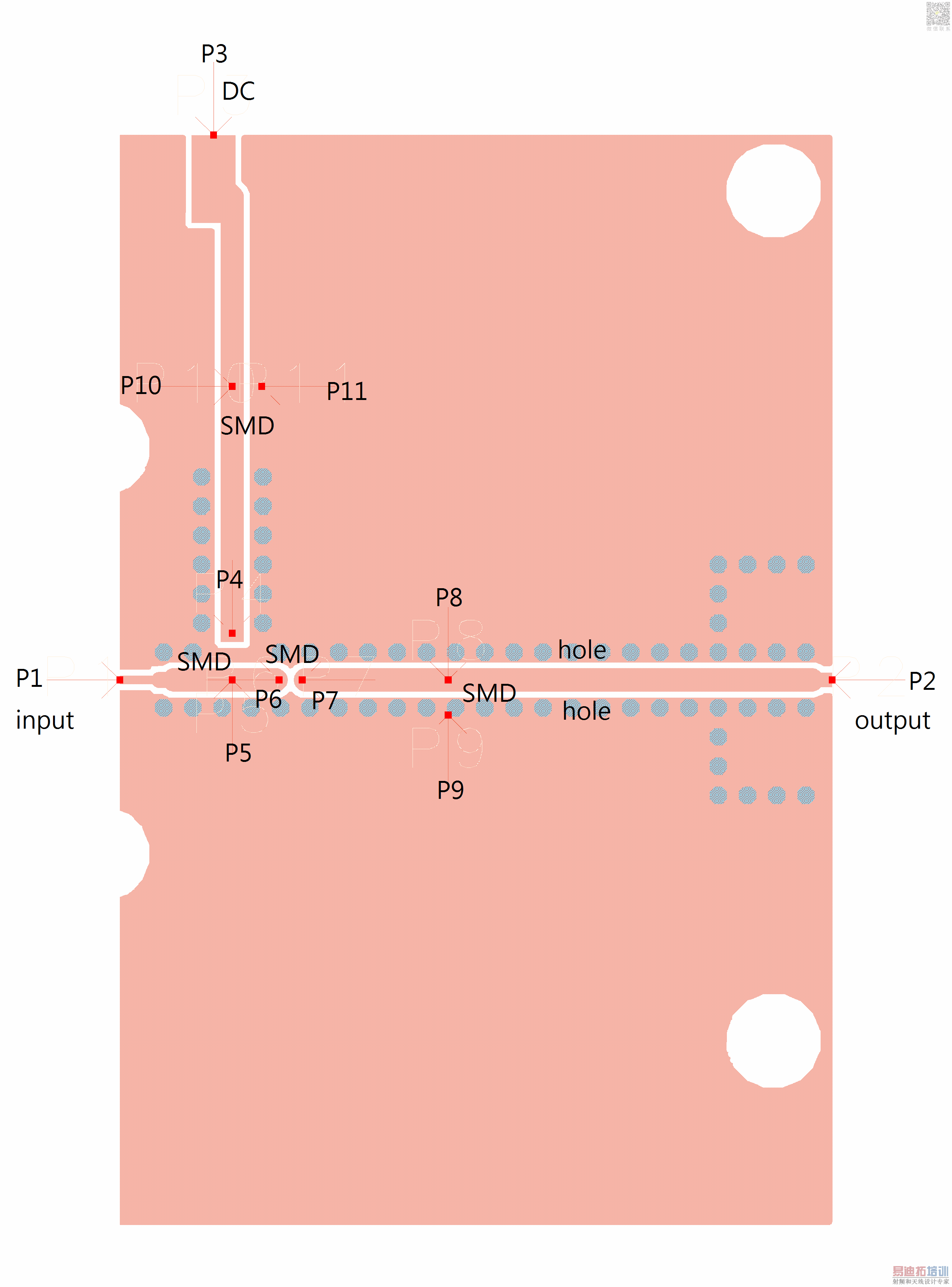

and I want to do the em-cosimulation in schematic to see the S11 at f=2.14GHz:
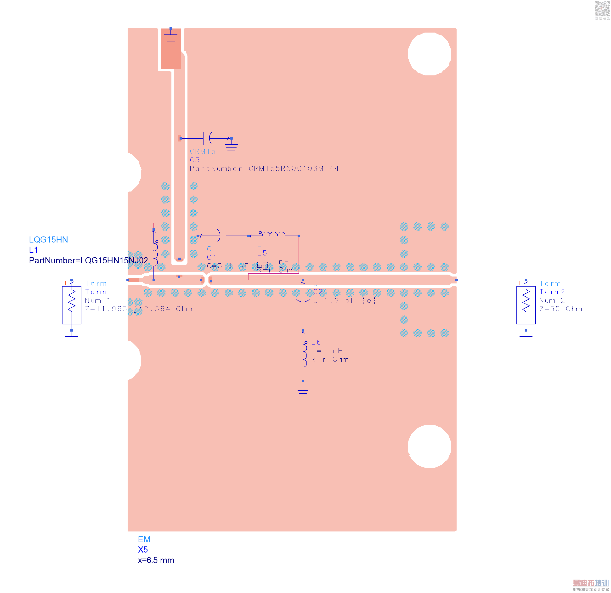
There are three different types in frequency plan of the em setup,which are adaptive,linear and single.

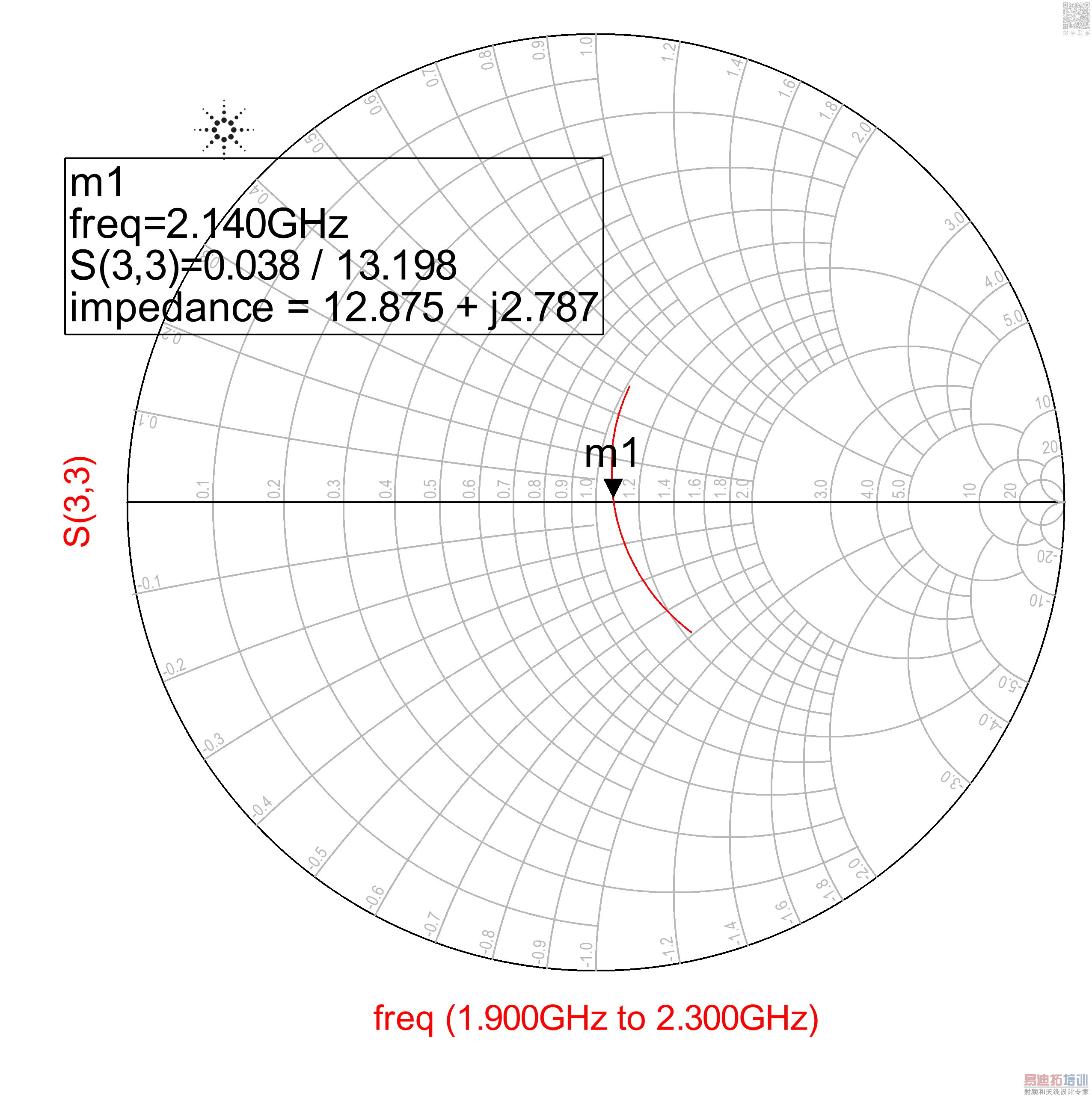
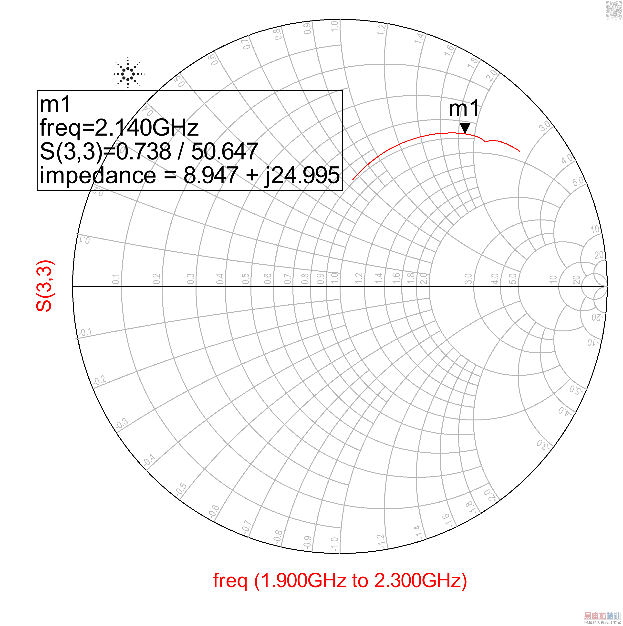
But the results of adaptive and linear are quite different:
adaptive:
linear:
single:
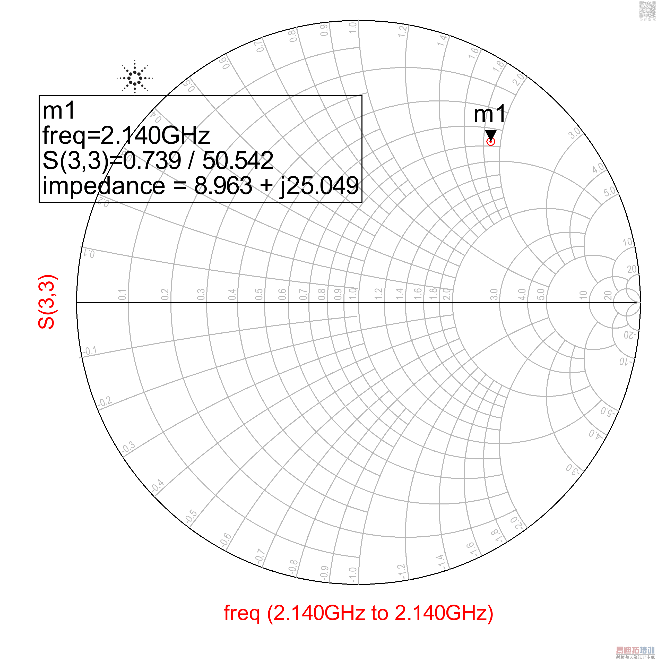
The result of single seems matched with the one of linear at f=2.14GHz.
But the result of linear isn't smooth,and has discontinuity.
Does anyone know why can not the results match?
Thanks for reply~
The reason is that for single, only one single frequency is EM simulated, as the name indicates. If you use that emModel for circuit simulation at other frequencies, please note that ADS does always only use the frequency set in the emSetup/emModel. It does not use the frequency from schematics for EM simulation. So with your single frequency setting, you get nonsense because the emModel must do extrapolation to cover the schematic frequency.
You need to set the emSetup/emModel frequency range large enough to cover the schematic frequency range.
Hi,volker, and thanks for your reply.
I am not sure if my question match to your reply.
I want to see the S11 at f=2.14GHz,
so I do the em-cosimulation with 3 different em setups.
(The sweep type setup is at the frequency plan tab of em setup, not at the schematic.)

There are three choices of sweep type I can use , which are linear, adaptive and single.
For the adaptive and linear, I sweep the frequency from 1.9~2.3GHz,but I just want to see the result at 2.14 GHz.
Sure, but you showed swept co-simulation results and I wanted to point out that single frequency EM settings are only useful with single frequency schematic sweep. Unlike other simulators, ADS does not pass the required schematic frequency settings to the EM solver.
All three results must be the same at 2.14GHz. If you use adaptive sweep, you can enfore an EM frequency at an exact frequency by adding a single point in addition to the sweep in emSetup. But adaptive sweep should be fine here. So basically, if you see a difference, it must be a difference (mistake) in your models. Some missing wire in connecting the co-simulation or another schematic difference between the cases. Otherwise, we expect identical (or almost identcal) results.
I am confused with the three results having a difference, but when I ran the simulation, I just changed the frequency type and didn't change the schematic and layout.
I have attached my workspace(2013 version), can you help me look at my design if you have time?
Thank you~~
ATF511P8_Narrowband_output_2.14G_wrk.7z
There must be something else that changed directly or indirectly. I'm too busy now to look at your model, but why don't you send it to Keysight support?
Ok,thank you.All your suggestions above really help me a lot. I will send my workspace to the keysight support.
Thank you volker.
I have found the answer to my problem.
When I change the impedance of the port 1 from 11.963-j*2.564 Ohm to 50 Ohm,
the results of linear and adaptive match together.
But I don't know why the complex impedance of the port will cause the mismatch.
I'm sure you compare apples and oranges. There is no technical reason why the sweep type could change results. The solver does the exact same thing at the same frequency.
OK, I got it.
申明:网友回复良莠不齐,仅供参考。如需专业帮助,请学习易迪拓培训专家讲授的ADS视频培训课程。
上一篇:Ads moment:how to simulate with different size of layers?
下一篇:how to find impedance of a rectifier circuit in ADS
 国内最全面、最专业的Agilent ADS培训课程,可以帮助您从零开始,全面系统学习ADS设计应用【More..】
- Agilent ADS教学培训课程套装
- 两周学会ADS2011、ADS2013视频教程
- ADS2012、ADS2013射频电路设计详解
- ADS高低阻抗线微带滤波器设计培训教程
- ADS混频器仿真分析实例视频培训课程
- ADS Momentum电磁仿真设计视频课程
- ADS射频电路与通信系统设计高级培训
- ADS Layout和电磁仿真设计培训视频
- ADS Workspace and Simulators Training Course
- ADS Circuit Simulation Training Course
- ADS Layout and EM Simulation Training Course
- Agilent ADS 内部原版培训教材合集
