- 易迪拓培训,专注于微波、射频、天线设计工程师的培养
impedance match on hardware level and ads stimulation
I'm interested to learn the impedance matching/tuning on a hardware with the helps on ADS stimulation.
Any material or case study/paper that i could download online and study the process of impedance matching/tuning.
For example, for transmitter development, i have a transceiver-PA-switch-duplexer-ant.
Let say i want to match the PA output to the ant to 50 ohm.
i starting by putting a calibrated pigtail on the PA output side, measure the original s11 of the transmission line with NA.
From there i could extract the s2p file and put it into stimulation.
yea, that pretty much i could think with my newbie knowledge.
Any detail and comprehensive document or paper i could study to master the whole process of s11 matching/tuning on hardware level with assistance on ADS stimulation circuit.
thanks.
http://edadocs.software.keysight.com...tching+Utility
hi thanks for the reply.
can i said that matching circuit is also some forms of filter, which reject the unwanted frequency and pass through the frequencies of interest?
Yes.
For example, you can reject image by using BandPass Matching before mixer.
See https://home.sandiego.edu/~ekim/e194.../matcher2.html
thanks!
i have a question, let say for designing a transmitter for GSM band 800.
I saw some designers can design the pi matching network with certain value of CAP and IND without running stimulation.
Is it because from the known transmit frequency, so they know what value of CAP and IND to put in to filter the unwanted freq and remain the transmitter frequency in the path ?
thanks
Describe correctly without any abbreviation.
Do you mean 800MHz band ?
What do you mean by "stimulation" ?
Show me detail of your PA.
Especially show me output configuration of your PA.
If your PA is a internal matching type, external pi network will be designed as bandpass filter or notch filter.
Anyway describe your situations in detail with correct terminologies.

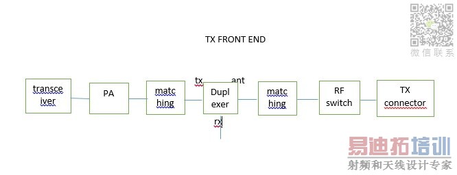
here is a simple block of a transmitter.
The connector is a port to measure our conducted tx power, after these portion is antenna part.
The PA is internally matched.
How do i design my both my matching circuitry.
Is it by connecting the connector port to a 50 ohm termination and solder a pigtail between PA and matching circuit to look at the s11 to the antenna direction? then match the patch to 50 ohm?
I can not understand what you want to mean at all.
Describe correctly.
sorry for all these typo...
i think i got the idea after went through some study.
thanks anyway.
申明:网友回复良莠不齐,仅供参考。如需专业帮助,请学习易迪拓培训专家讲授的ADS视频培训课程。
上一篇:Problem with importing IBIS model into ADS
下一篇:Question Regarding ADS
 国内最全面、最专业的Agilent ADS培训课程,可以帮助您从零开始,全面系统学习ADS设计应用【More..】
- Agilent ADS教学培训课程套装
- 两周学会ADS2011、ADS2013视频教程
- ADS2012、ADS2013射频电路设计详解
- ADS高低阻抗线微带滤波器设计培训教程
- ADS混频器仿真分析实例视频培训课程
- ADS Momentum电磁仿真设计视频课程
- ADS射频电路与通信系统设计高级培训
- ADS Layout和电磁仿真设计培训视频
- ADS Workspace and Simulators Training Course
- ADS Circuit Simulation Training Course
- ADS Layout and EM Simulation Training Course
- Agilent ADS 内部原版培训教材合集
