- 易迪拓培训,专注于微波、射频、天线设计工程师的培养
stepped impedance resonator design in ADS
录入:edatop.com 点击:
Hi everybody
I simulated a common SIR (attached paper) in ADS
but the result isn't correct
can u help me?
I simulated a common SIR (attached paper) in ADS
but the result isn't correct
can u help me?

If you casacde lines with different widths, you should include MSTEP elements that describe the electrical effect of that step. The MLIN element only includes the electrical model of the line.
Or in other words, if you do not include MSTEP elements, you might get a stepped-impedance low-pass characteristic response.
Agreed, without the MSTEP results are not totally different. But simulating with MSTEP is more accurate than cascading just the MLIN. And in some cases (extreme step in width at short line length, where we can't treat this as individual elements) all this model based simulation is not good enough and we need EM simulation to get really accurate results.
Agreed, without the MSTEP results are not totally different. But simulating with MSTEP is more accurate than cascading just the MLIN. And in some cases (extreme step in width at short line length, where we can't treat this as individual elements) all this model based simulation is not good enough and we need EM simulation to get really accurate results.
@laperla, what do you think is wrong with your result? It shows basic stepped impedance low pass response.
NLINE has only W and L and doesn't have Teta(Electrical lenght)
SIR is a typical resonator but in S21 I don't see any resonance. Base on this paper this resonator has to resonance in 1.5G
You confused me because you have MSUB block, but then didn't use microstrip lines.
You used ideal lines - is the 2GHz frequency the correct frequency for this phase value?
You mentioned a paper/reference, but forgot to include that, so nobody knows what results you expect.
You confused me because you have MSUB block, but then didn't use microstrip lines.
You used ideal lines - is the 2GHz frequency the correct frequency for this phase value?
You mentioned a paper/reference, but forgot to include that, so nobody knows what results you expect.
What you have drawn is a low pass, and the results that you show are low pass results.
for defining substrate, I used MSUB block...Should I use other block?
That is fine - but it only has an effect for MLIN and other microstrip lines. It has NO effect for your ideal lines, of course.
I cann't define Teta with MLIN
Now, How can I show of S21 with resonance at 1.5GHz?
Yes, of course. You must convert electrical parameters to physical dimensions. One way to do this from the ADS schematic window: Tools > Linecalc.
?
I did it but it doesn't change
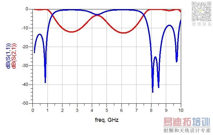
Yes, this is the correct result for your layout (lowpass).
Here is the result from another simulator (EM) for the same layout:


I attach the paper here...this schematic has to resonance!
Yes, but it is a totally completely different layout. The resonators are coupled to the feedlines with coupled lines (gap). In your case, you have placed ports on the resonator - totally different.
you mean that the couple SIR work as resonator?
and I have to consider both coupled SIR?
Yes, you must include the coupling structures (coupled lines with gap) to make it a resonator. With the ports directly connected, it works as a low pass filter.
申明:网友回复良莠不齐,仅供参考。如需专业帮助,请学习易迪拓培训专家讲授的ADS视频培训课程。
上一篇:Dear all experts, I need your help for Agilent ADS 2015 libraries
下一篇:a question:the accuracy of ads moment ?
ADS培训课程推荐详情>>
 国内最全面、最专业的Agilent ADS培训课程,可以帮助您从零开始,全面系统学习ADS设计应用【More..】
- Agilent ADS教学培训课程套装
- 两周学会ADS2011、ADS2013视频教程
- ADS2012、ADS2013射频电路设计详解
- ADS高低阻抗线微带滤波器设计培训教程
- ADS混频器仿真分析实例视频培训课程
- ADS Momentum电磁仿真设计视频课程
- ADS射频电路与通信系统设计高级培训
- ADS Layout和电磁仿真设计培训视频
- ADS Workspace and Simulators Training Course
- ADS Circuit Simulation Training Course
- ADS Layout and EM Simulation Training Course
- Agilent ADS 内部原版培训教材合集