- 易迪拓培训,专注于微波、射频、天线设计工程师的培养
caculate Zin of a HF rectifier using ADS
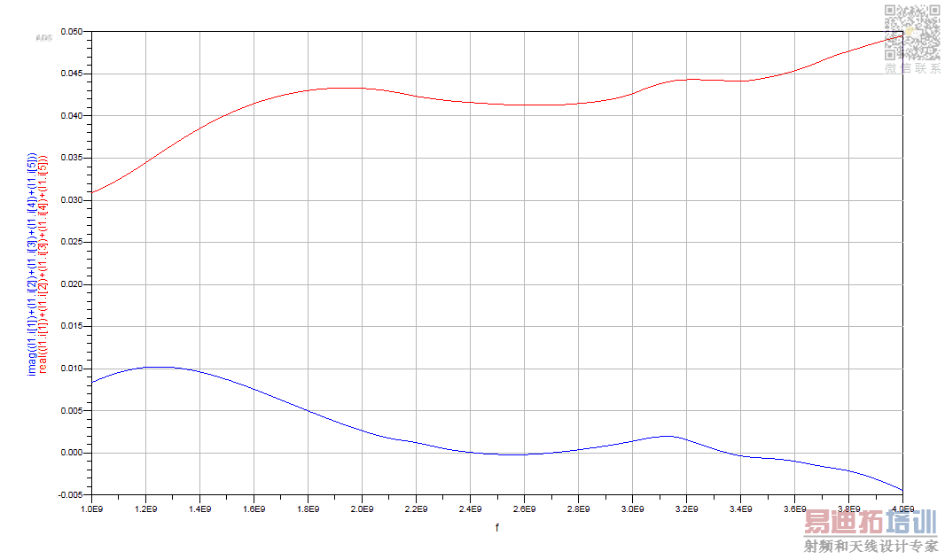
I?m a student majoring in EE. I want to design a wide-band high-efficiency rectifier for wireless power transmission based on the paper below. I used the same diode as it said: HSMS286c in HFDiode lib. I used the variable 'f' to simulate the Zin in different frequencies. However, the verdict is different from the paper's result and I have no idea why. The imag part is positive but it should be negative. Perhaps I set something wrongly.
What should I do about it?Can any of you help?
Thank you so much.
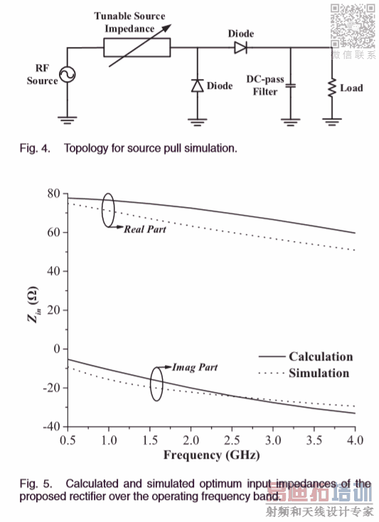

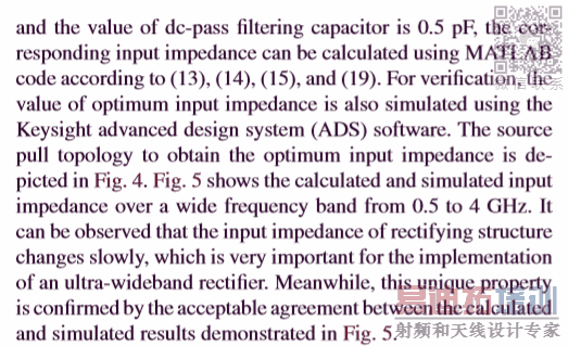
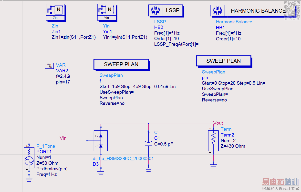
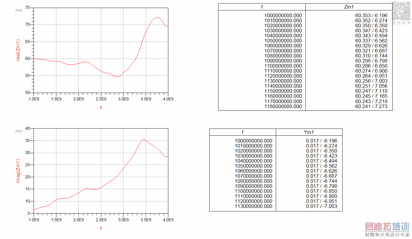
-You do a methodology error.Don't use LSSP, instead use HB and place Current Meter at the input and simply divide V/I ( complex impedance) because rectifiers are highly nonlinear systems.
-The author used a tunable source impedance and you should imitate the same thing.
The paper's title is Shaoyong Zheng's Design of an Ultra-Wideband High-Efficiency Rectifier for Wireless Power Transmission and Harvesting Applications.
You can use LSSP.
However LSSP is not so useful for rectifier.
See https://www.edaboard.com/showthread.php?354542
Hi, I'm new to ADS and I'm puzzled right now. I think the tunable source impedance means matching network which I can only add after measuring the Zin. Can I still use this source? I wanted to change it into AC power, however, this paper never mentioned the Vin or Iin, I only know Pin is 17dBm. To be more clear, the proposed rectifier in this paper is attached as follows. Thank you so much for answering my questions.
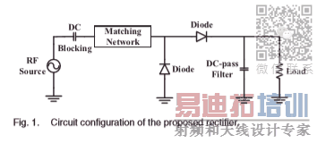

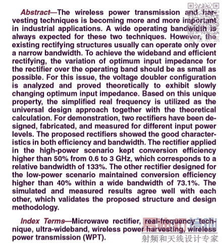

Thanks a lot, I get it. Did I set the input right? And could you tell me how to calculate Vin/Iin, please? I'm really confused. Thank you so much for your help!

申明:网友回复良莠不齐,仅供参考。如需专业帮助,请学习易迪拓培训专家讲授的ADS视频培训课程。
上一篇:who can give us some examples about Mixer Design by ADS
下一篇:How to import ADS data to MATLAB
 国内最全面、最专业的Agilent ADS培训课程,可以帮助您从零开始,全面系统学习ADS设计应用【More..】
- Agilent ADS教学培训课程套装
- 两周学会ADS2011、ADS2013视频教程
- ADS2012、ADS2013射频电路设计详解
- ADS高低阻抗线微带滤波器设计培训教程
- ADS混频器仿真分析实例视频培训课程
- ADS Momentum电磁仿真设计视频课程
- ADS射频电路与通信系统设计高级培训
- ADS Layout和电磁仿真设计培训视频
- ADS Workspace and Simulators Training Course
- ADS Circuit Simulation Training Course
- ADS Layout and EM Simulation Training Course
- Agilent ADS 内部原版培训教材合集
