- 易迪拓培训,专注于微波、射频、天线设计工程师的培养
Frequency Multipier in ADS
录入:edatop.com 点击:
Hello,
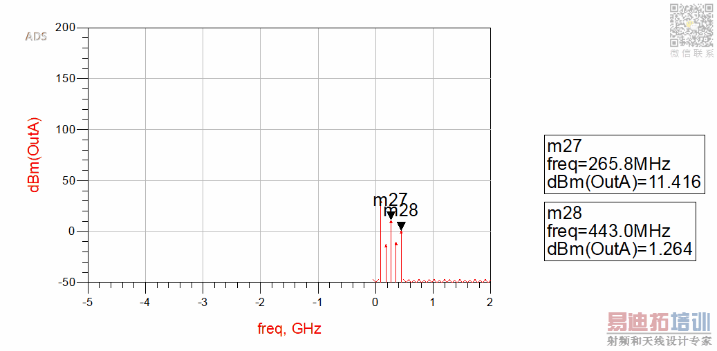
I have designed and simulated a frequency multiplier in ADS but my result is not acceptable. My Frequency multiplier conversion loss is shown below.
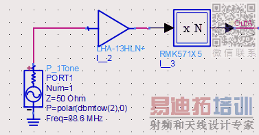
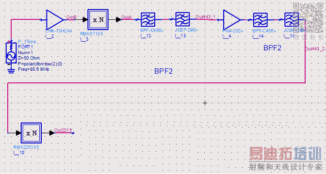
Here is my circuit.
Here is my settings.
why the third and fifth harmonics of Frequency multiplier aren't the same? Because and regarding the datasheet, The third and fifth harmonics have the same power gain( I have set 0db for third harmonic which has the same power gain related to fifth harmonic)
Did I make a mistake?
Based on ADS tutorial:
https://edadocs.software.keysight.co...pageId=6083662
but I get the same result.
Thank you. I assumed as well, but based on Keysight tutorial "G3 Power gain of third harmonic relative to input tone" so the datasheet and G3 parameters are the same. However, I simulated your suggestion but I got this:
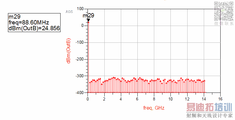
I just simulated my amplifier and I got this result. By injecting 2dbm I got 24dbm amplified signal.
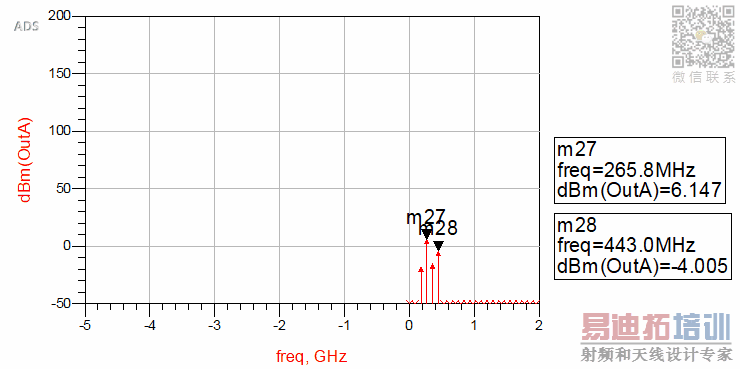
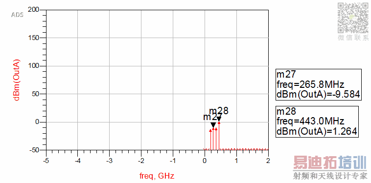
As you can see in the first diagram everything is good but in the second stage strange frequency appeared.
For example where did 2.126Ghz frequency come from?
Thanks
I have designed and simulated a frequency multiplier in ADS but my result is not acceptable. My Frequency multiplier conversion loss is shown below.

Here is my circuit.
Here is my settings.
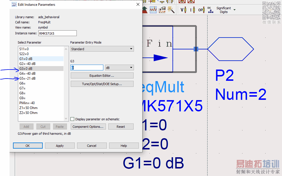
why the third and fifth harmonics of Frequency multiplier aren't the same? Because and regarding the datasheet, The third and fifth harmonics have the same power gain( I have set 0db for third harmonic which has the same power gain related to fifth harmonic)
Did I make a mistake?
Based on ADS tutorial:
https://edadocs.software.keysight.co...pageId=6083662
Both components are 50-ohm matched, maybe models have some parameters like supply voltage?
I would try to put DC-blocks around LHA-13HLN
Your parameter settings don't comply with the datasheet. Notice that harmonic levels are relative to 5th harmonic output. If G5 is -21dB, G3 should have a similar value.
I really appreciate your help
I created a Data items and add LHA-13HLN s-parameters touch stone so it doesn't have any supply voltage. However, I check the circuit by removing the amplifier
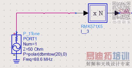
but I get the same result.
Thank you. I assumed as well, but based on Keysight tutorial "G3 Power gain of third harmonic relative to input tone" so the datasheet and G3 parameters are the same. However, I simulated your suggestion but I got this:
I just simulated my amplifier and I got this result. By injecting 2dbm I got 24dbm amplified signal.
Not the same, datasheet value is relative to output level.
Neither in post #1 nor post #4, 3rd and 5th harmonic have similar level. About 10 dB difference, but with opposite direction. So there's obviously an additional effect in the model behavior.
Sure you have set HB analysis parameters appropriately?
Yes , you are right. I made a mistake not to take into account the "Input" and "Output" words.
I changed and made my circuit bigger. Here is my present circuit (double mixer) (5X , 5X) I set my input frequency order in harmonic balance simulation about 150.
As you can see in the first diagram everything is good but in the second stage strange frequency appeared.
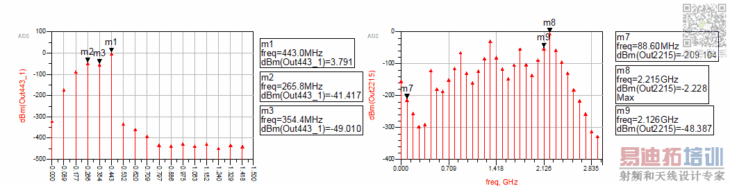
For example where did 2.126Ghz frequency come from?
Thanks
Unwanted output signal is mixing product of 4th harmonic (354 MHz) which isn't significantly attenuated by the bandpass filter.
Thank you, how did the 4th harmonic of (354Mhz) generate with that high amplitude? the frequency multiplier mentioned it has low harmonics and IM components.
申明:网友回复良莠不齐,仅供参考。如需专业帮助,请学习易迪拓培训专家讲授的ADS视频培训课程。
上一篇:Impedance mathing s2p file in ads
下一篇:Re: Doubts on SMT components in ADS
ADS培训课程推荐详情>>
 国内最全面、最专业的Agilent ADS培训课程,可以帮助您从零开始,全面系统学习ADS设计应用【More..】
- Agilent ADS教学培训课程套装
- 两周学会ADS2011、ADS2013视频教程
- ADS2012、ADS2013射频电路设计详解
- ADS高低阻抗线微带滤波器设计培训教程
- ADS混频器仿真分析实例视频培训课程
- ADS Momentum电磁仿真设计视频课程
- ADS射频电路与通信系统设计高级培训
- ADS Layout和电磁仿真设计培训视频
- ADS Workspace and Simulators Training Course
- ADS Circuit Simulation Training Course
- ADS Layout and EM Simulation Training Course
- Agilent ADS 内部原版培训教材合集