- 易迪拓培训,专注于微波、射频、天线设计工程师的培养
Problem with ADS em simulation for dualband filter
录入:edatop.com 点击:
Hi guys, im trying to simulate a dual-band microstrip filter in ADS with the frequency at 2.4Ghz to 5Ghz.
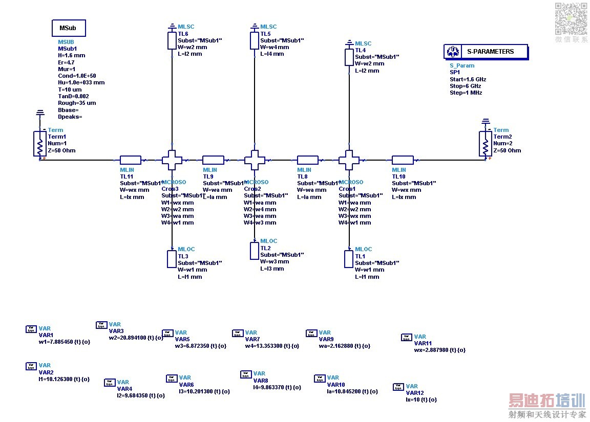
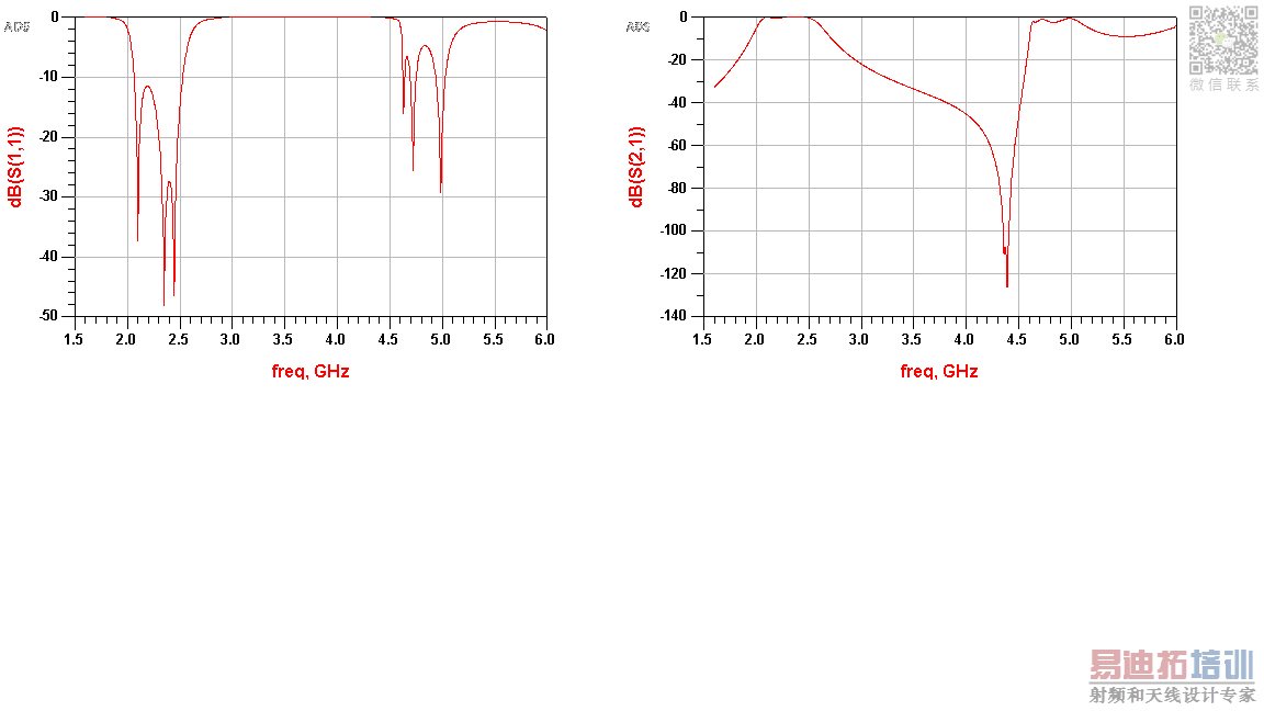
I've already have all my components designed using tlines-microstrip and its under (jpeg1) and the graph obtained is under (jpeg2).
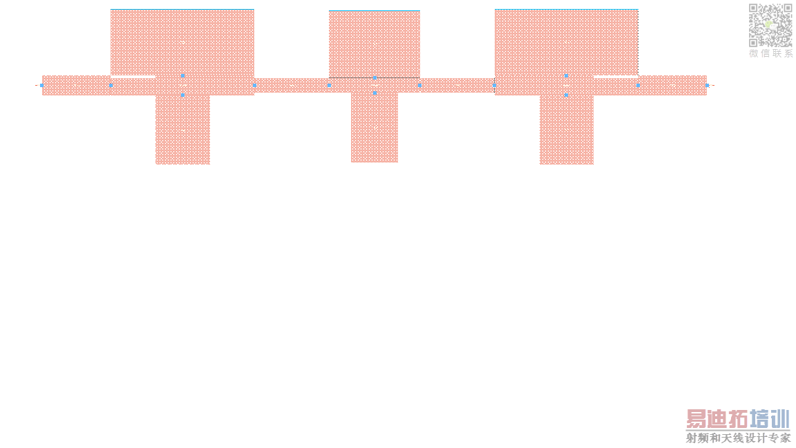
The problem occurs when i convert my filter into layout design(jpeg3) in ads.
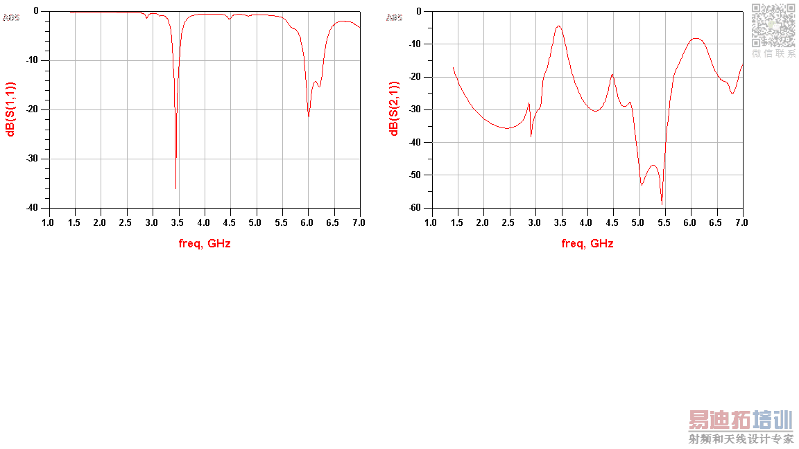
The graph obtain through em simulation seems to be very weird and seems to be 1GHz shifted.(jpeg4)
For em simulation:
substrate fr4=4.7 dieelctric constant
height=1.6mm
frequency plan=1.4GHz to 7GHz, Npts=50
Ive tried changing the frequency plans , Npts and the frequency type to adaptive but nothing changes
Could you guys help me figure out the problem? Thank you
jpeg1
jpeg2
jpeg3
jpeg4
I've already have all my components designed using tlines-microstrip and its under (jpeg1) and the graph obtained is under (jpeg2).
The problem occurs when i convert my filter into layout design(jpeg3) in ads.
The graph obtain through em simulation seems to be very weird and seems to be 1GHz shifted.(jpeg4)
For em simulation:
substrate fr4=4.7 dieelctric constant
height=1.6mm
frequency plan=1.4GHz to 7GHz, Npts=50
Ive tried changing the frequency plans , Npts and the frequency type to adaptive but nothing changes
Could you guys help me figure out the problem? Thank you
jpeg1

jpeg2

jpeg3

jpeg4

I doubt that the TL crosspoint model can be applied to the extreme stub widths in the actual implementation. The assumption of a 1-D wave transmission isn't met. The edges of the shunt stubs seem even to touch the series stubs.
申明:网友回复良莠不齐,仅供参考。如需专业帮助,请学习易迪拓培训专家讲授的ADS视频培训课程。
ADS培训课程推荐详情>>
 国内最全面、最专业的Agilent ADS培训课程,可以帮助您从零开始,全面系统学习ADS设计应用【More..】
- Agilent ADS教学培训课程套装
- 两周学会ADS2011、ADS2013视频教程
- ADS2012、ADS2013射频电路设计详解
- ADS高低阻抗线微带滤波器设计培训教程
- ADS混频器仿真分析实例视频培训课程
- ADS Momentum电磁仿真设计视频课程
- ADS射频电路与通信系统设计高级培训
- ADS Layout和电磁仿真设计培训视频
- ADS Workspace and Simulators Training Course
- ADS Circuit Simulation Training Course
- ADS Layout and EM Simulation Training Course
- Agilent ADS 内部原版培训教材合集
