- 易迪拓培训,专注于微波、射频、天线设计工程师的培养
Phase Shift Oscillator Simulation in ADS
录入:edatop.com 点击:
Hi All,
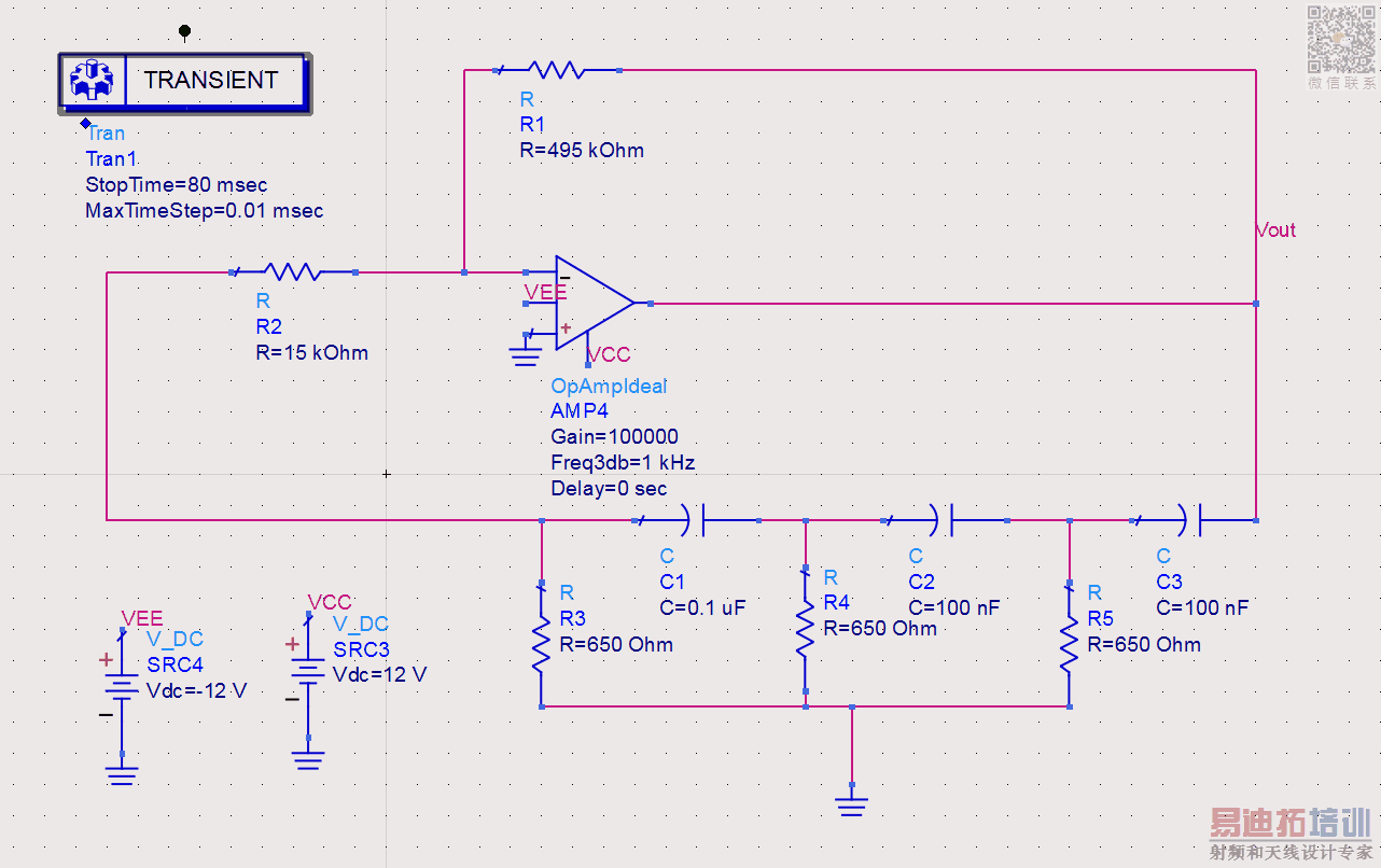
I've been trying to simulate the circuit in the attached image, but not getting the results I want.
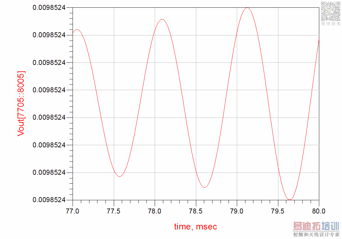
The oscillations seem ok, but the magnitude is far off and been going round in circles trying different things.
#In ADS, there's an Ideal OpAmp and standard model; in the schematic attached, I've used the Ideal model, but the example that I'm trying to follow seems to be using the standard model, which I've tried and cannot get the same results. The book that I'm following was published around 2006, so they have been using the older ADS where I think the Ideal wasn't available.
Anyway, if anyone can spot where I'm going wrong or pass any advice would be great.
Thanks in advance,
Hakim
I've been trying to simulate the circuit in the attached image, but not getting the results I want.
The oscillations seem ok, but the magnitude is far off and been going round in circles trying different things.
#In ADS, there's an Ideal OpAmp and standard model; in the schematic attached, I've used the Ideal model, but the example that I'm trying to follow seems to be using the standard model, which I've tried and cannot get the same results. The book that I'm following was published around 2006, so they have been using the older ADS where I think the Ideal wasn't available.
Anyway, if anyone can spot where I'm going wrong or pass any advice would be great.
Thanks in advance,
Hakim

Have you ever tried to increase Freq3dB parameter of the OpAmp to higher value ? I guess OpAmp is working at limit of its frequency response and therefore sufficient amplification doesn't occur..
Yes, just tried it and stays the same. If you were do this using the normal model, what parameters would you configure in the model below:
http://cp.literature.agilent.com/lit...lifier%29.html
Here's the ideal model as well:
http://edadocs.software.keysight.com...ageId=58327394
I have also tried setting the frequency in the transient simulator, but don't really understand what happens with that and just doing a bit of hit & hope at the moment
Oscillator simulations in ANY simulator-professional or not- need always-more or less-a triggering circuit to wake -up the circuit because the simulator takes the DC simulation OP data and apply its own stimulus to excite the circuit and it does not frequently work.Therefore we should artificially trig/excite the circuit like below.The R-C Oscillator frequency is approx. 990kHz.a HB simulation should be done to find the exact oscillation frequency.
I have simply applied an "Initial Condition" block and it has started to oscillate..


Dont sweat it much, nobody ever uses a phase shift oscillator when there are much better designs to give stable clock or pure sine wave.
Its best purpose is to teach you if you try this in some feed forward or feedback cascade filter. It might oscillate. Bode plots can demonstrate this.Also you wont get rail to rail outputs with BJT outputs and you should use R>1K then for CMOS outputs use R>10K to avoid loading factor on output.
Nice one BigBoss,
No I get what your saying, as i did a lot of control theory last year and should have known that. But thanks again.
Yes you're right, I'm just studying this on my high frequency electronics module and wanted to see it working.
If I understand the document right, the "ideal opamp" doesn't implement output saturation. The terminal you have connected to VCC and VEE are not supply nodes rather than input and output reference potentials which would be usually connected to GND. It's impossible to get meaningful oscillator simulation using this component without additional means.
The "real opamp" component should work, also any kind amplifier model with output saturation respectively voltage limiting. As an additional point, oscillator simulation may need an initial "kick start" or non-equilibrium state. Both points have been already clarified by BigBoss.
A better design uses diodes or simply transistor differential pair for soft limiting, then you always get a sine wave out. With OA you don't as gain switch from linear 1e6 to zero in saturation is too high.
申明:网友回复良莠不齐,仅供参考。如需专业帮助,请学习易迪拓培训专家讲授的ADS视频培训课程。
上一篇:How can i measure inter modulation distortion of a RF Mixer circuit in ADS?
下一篇:Doubt regarding on the Thin Film Resistor(TFR) in ADS
ADS培训课程推荐详情>>
 国内最全面、最专业的Agilent ADS培训课程,可以帮助您从零开始,全面系统学习ADS设计应用【More..】
- Agilent ADS教学培训课程套装
- 两周学会ADS2011、ADS2013视频教程
- ADS2012、ADS2013射频电路设计详解
- ADS高低阻抗线微带滤波器设计培训教程
- ADS混频器仿真分析实例视频培训课程
- ADS Momentum电磁仿真设计视频课程
- ADS射频电路与通信系统设计高级培训
- ADS Layout和电磁仿真设计培训视频
- ADS Workspace and Simulators Training Course
- ADS Circuit Simulation Training Course
- ADS Layout and EM Simulation Training Course
- Agilent ADS 内部原版培训教材合集