- 易迪拓培训,专注于微波、射频、天线设计工程师的培养
Confused with LNA bilateral conjugate design using ADS, please help

I am trying to design the input and output matching network for BGA2001 LNA at 1.6GHz and simulate the design in ADS. There are two ways for bilateral design. First method is as follows:
1) Draw the Ga constant gain circles and noise figure circles, then select a optimum source reflection Γs point on the smith chart by balancing between Ga gain and noise figure.
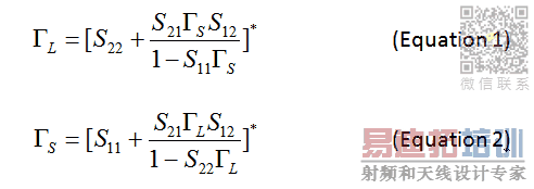
2) Calculate the corresponding ΓL based on the selected Γs above using equation 1 in the attached image.
3) Matching both Γs and ΓL to 50 Ohm.
The second method is as follows,
1) Draw the Gp constant gain circles at 1.6GHz, then select a optimum load reflection ΓL point on the smith chart based on target Gp gain values.
2) Calculate the corresponding Γs based on the selected ΓL above using equation 2 in the attached image.
3) Matching both Γs and ΓL to 50 Ohm.
I then did the AC simulation after impedance matching for both methods above, but what made me very confused is the difference between the simulation results. I selected both 20 dB gain for Ga gain in the first method and Gp gain in the second method, and the simulation result shows the second method has perfect 20 dB output but the result of the first method based on Ga circles has much lower output of 17 dB, 3dB below my expectation. I checked again and again there are no calculation errors. The only thing in the first method is that the calculated ΓL is not far from the load stability circle but still stable.
Did anyone come across this problem? I prefer the first method as it takes the noise figure into account but why it generates much lower gain? Could anybody answer my question and clear my confusion?
Thanks and regards.
I need to clarify this. I measured point immediately after the LNA (here I call it Gain1) and the point after the LC output matching network(here I call it Gain2). Gain1 is higher than 20dB (I tried several parameters and Gain1 is as high as 22.9dB), but Gain2 dropped to around 17 dB, which means the output matching network caused at least 3dB gain loss. There will be a mixer right after the output matching network. Does that mean I do not need to do the bilateral conjugate matching at all because without any matching the simulated gain is also around 17 dB?
申明:网友回复良莠不齐,仅供参考。如需专业帮助,请学习易迪拓培训专家讲授的ADS视频培训课程。
上一篇:Using ADS to design a 802.11p 5.9 GHz PA
下一篇:Low Noise Block on ADS Design
 国内最全面、最专业的Agilent ADS培训课程,可以帮助您从零开始,全面系统学习ADS设计应用【More..】
- Agilent ADS教学培训课程套装
- 两周学会ADS2011、ADS2013视频教程
- ADS2012、ADS2013射频电路设计详解
- ADS高低阻抗线微带滤波器设计培训教程
- ADS混频器仿真分析实例视频培训课程
- ADS Momentum电磁仿真设计视频课程
- ADS射频电路与通信系统设计高级培训
- ADS Layout和电磁仿真设计培训视频
- ADS Workspace and Simulators Training Course
- ADS Circuit Simulation Training Course
- ADS Layout and EM Simulation Training Course
- Agilent ADS 内部原版培训教材合集
