- 易迪拓培训,专注于微波、射频、天线设计工程师的培养
dc load line in ADS.
i going to design power amplifier by ADS .but in DC simulation i cant plot load line inn I-V curve. can help me?
In ADS Component Palette, there is a IV Curve Tracer element to obtain for BJT and FET transistors.Use that..
thanks for your guide .and how can i select best point in IV curve for (for example) AB class power amp?
"The Best Point" is quite variable for the active device which you intend to use.Therefore, you should select a appropriate point and then try to optimize this OP in according to you specifications.
I recommend Load Pull technique to find a compromised OP.
where can i find IV curve tracer?
You have 2 options to do this. Either:
Create a new schematic design, using File > New Design... from any open schematic window, and in the New Design window under the "Schematic Design Template (Optional)" select the drop down list and pick either BJT_curver_tracer or FET_curver_tracer as required. Add you device to the schematic and connect as appropriate.
Or
Open the "Simulation - Instrument" palette and add either the "DC BJT" or "DC FET" curve tracer symbol to an existing schematic design. Then connect the Base/Collector or Gate/Drain pins to the device to be tested.
:
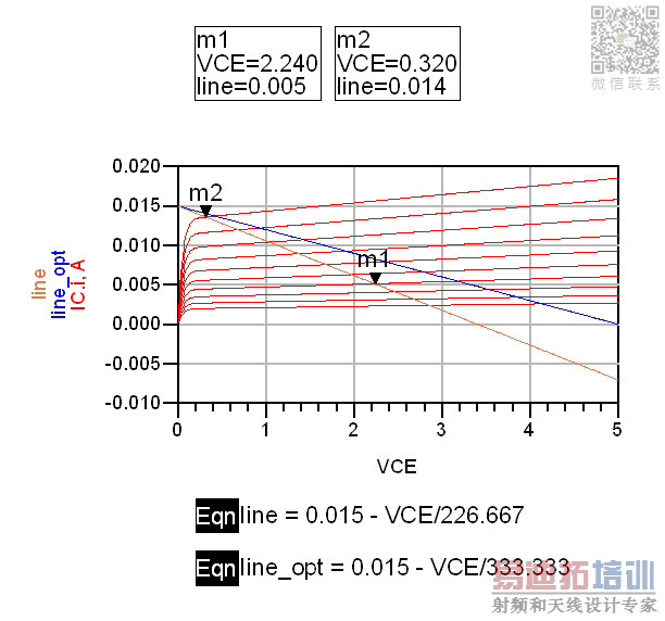
this module (DC_FET) can plot just IV curve i am seeking the manner that plot load line on IV curve like this image :
http://obrazki.elektroda.pl/8217285300_1390335972.jpg
and which can i select best point for AB amp?
Those 2 load lines appear to be simply equations that we manually added to the graph display for the IV curves. Something like this:

thanks for your guide. but a question : what is the constant parameter (for example .015 , 226.667 in line equation ) ? for my FET model how can i determine them? I'm sorry for the stupid question
These are just numbers that happen to work for the example case. The 0.015 is the point where the line crosses the Y axis and represents the maximum current through the transistor. The 226/333 numbers are the slope of the load line and would represents some sort of (load) resistance. There is no way to get ADS to automatically generated these lines I just demonstrated a method of entering them manually.
how can i determine maximum current?
or how can i determine load resistance?
How can I determine maximum current or load resistance?
申明:网友回复良莠不齐,仅供参考。如需专业帮助,请学习易迪拓培训专家讲授的ADS视频培训课程。
上一篇:How to simulate NFdsb & NFssb of a mixer using ADS ?
下一篇:How to draw a split ring resonator in ADS momentum
 国内最全面、最专业的Agilent ADS培训课程,可以帮助您从零开始,全面系统学习ADS设计应用【More..】
- Agilent ADS教学培训课程套装
- 两周学会ADS2011、ADS2013视频教程
- ADS2012、ADS2013射频电路设计详解
- ADS高低阻抗线微带滤波器设计培训教程
- ADS混频器仿真分析实例视频培训课程
- ADS Momentum电磁仿真设计视频课程
- ADS射频电路与通信系统设计高级培训
- ADS Layout和电磁仿真设计培训视频
- ADS Workspace and Simulators Training Course
- ADS Circuit Simulation Training Course
- ADS Layout and EM Simulation Training Course
- Agilent ADS 内部原版培训教材合集
