- 易迪拓培训,专注于微波、射频、天线设计工程师的培养
how to simulation differential filter by ads,plz help
录入:edatop.com 点击:
recently i study differential filter,but i only simulate single-ended signal before.
could anyone give me some pdf to show how to simulate differential filter by ads,thanks in advance!
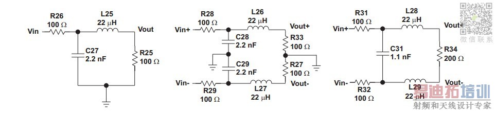
where L1 L2 L3 L4 L5 are inductors and C1 and C2 are capacitors.
The filter was designed for 50ohm impedance matching both for input port and output port.
After conversion to differential filter the result is this:
So let us say in order to design 100 ohm differential filter you have to first synthesize 50 ohm single ended filter and then convert it to differential.
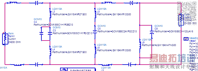
From simulation perspective, you have to remove ground pins from port termination and connect it to your circuit. Attached image.
I hope this will help you to start your simulations in ADS.
Let me know if you need any more information.
Cheers,
Antonio.
there is some warning,should i ingnore it?
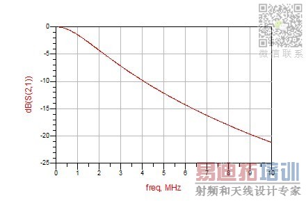
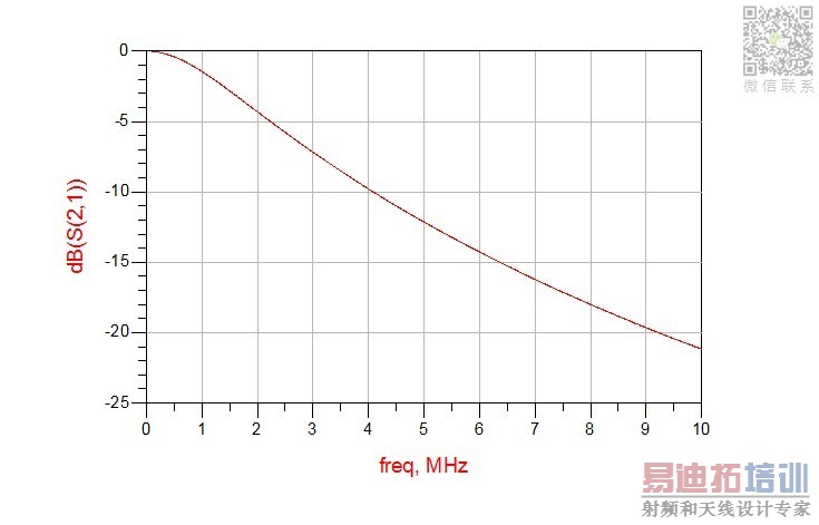
and my result is not the same as the pdf"image,on pfd'image s21 is -40dB on 10MHz,my result is -20dB on 10MHz,so i feel like i didnt do it the right way,please help me
- - - Updated - - -
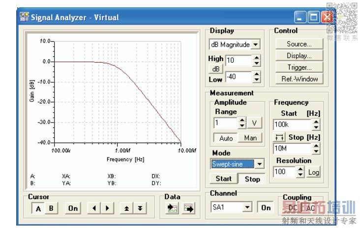
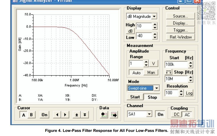
and the pdf"image shows there shoud be -40dm on the freq of 10MHZ as below:
but when i simulate it by ads as below:
http://obrazki.elektroda.pl/2698684200_1357723796.jpg
the result is different,only -20db at 10MHZ
PLEASE,HELP ME,thank you
could anyone give me some pdf to show how to simulate differential filter by ads,thanks in advance!
Hi,
I hope you know the process of converting single ended filter to differential filter. If not, then follow this document which will give you some idea on how to convert single ended filter to differential.
http://www.ti.com/lit/an/slwa053b/slwa053b.pdf
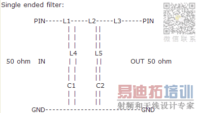
where L1 L2 L3 L4 L5 are inductors and C1 and C2 are capacitors.
The filter was designed for 50ohm impedance matching both for input port and output port.
After conversion to differential filter the result is this:
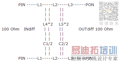
So let us say in order to design 100 ohm differential filter you have to first synthesize 50 ohm single ended filter and then convert it to differential.
From simulation perspective, you have to remove ground pins from port termination and connect it to your circuit. Attached image.
I hope this will help you to start your simulations in ADS.
Let me know if you need any more information.
Cheers,
Antonio.
thank you ,your pdf really helps me a lot ,here is what i do,but i dont know if am i right

there is some warning,should i ingnore it?
and my result is not the same as the pdf"image,on pfd'image s21 is -40dB on 10MHz,my result is -20dB on 10MHz,so i feel like i didnt do it the right way,please help me
- - - Updated - - -
Hi,
I am happy that pdf helped you in getting understanding about single ended to differential filter conversion.
First of all I am not able to view any of your uploaded images in large size. So it is very difficult for me to comment on what did you synthesized and what did you simulated in ADS.
1. Could you please update on filter specifications you are trying to meet and also upload images properly so that I can view them properly ?
2. What was your synthesis impedance ?
3. Yes, you can ignore the warning as it will look for ground node.
4. What tool are you using for synthesis ?
Please give some information as requested above so that I can help you better.
Cheers,
Antonio
i did it just as pdf told me.
and the pdf"image shows there shoud be -40dm on the freq of 10MHZ as below:
but when i simulate it by ads as below:

http://obrazki.elektroda.pl/2698684200_1357723796.jpg
the result is different,only -20db at 10MHZ
PLEASE,HELP ME,thank you
Your ADS schematic has 2.2μH instead of 22μH.
so careless,shame of myself
- -!
申明:网友回复良莠不齐,仅供参考。如需专业帮助,请学习易迪拓培训专家讲授的ADS视频培训课程。
上一篇:how to plot the VSWR in ADS software
下一篇:Modelling SPDT switch in ADS
ADS培训课程推荐详情>>
 国内最全面、最专业的Agilent ADS培训课程,可以帮助您从零开始,全面系统学习ADS设计应用【More..】
- Agilent ADS教学培训课程套装
- 两周学会ADS2011、ADS2013视频教程
- ADS2012、ADS2013射频电路设计详解
- ADS高低阻抗线微带滤波器设计培训教程
- ADS混频器仿真分析实例视频培训课程
- ADS Momentum电磁仿真设计视频课程
- ADS射频电路与通信系统设计高级培训
- ADS Layout和电磁仿真设计培训视频
- ADS Workspace and Simulators Training Course
- ADS Circuit Simulation Training Course
- ADS Layout and EM Simulation Training Course
- Agilent ADS 内部原版培训教材合集