- 易迪拓培训,专注于微波、射频、天线设计工程师的培养
LNA design on ADS2009
I designed an LNA working at 5.8GHz operating frequency. I simulate it on ADS2009. Here are the results.
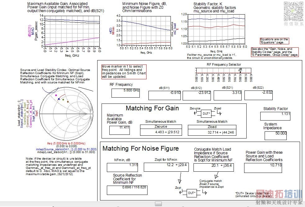
I am new on ADS.I used AWR and got better results on AWR by changing microstripline dimensions of layout. Can i do this on ADS and how?
I want to get better results.
Thanks.
ADS training videos:
http://www.rf-design-tips.com/ads-qu...line-training/
Part a - Tuning and Variables in Advanced Design System
Part b - Tuning and Variables in Advanced Design System
The Optimization Cockpit in ADS
so many thanks guys. really i got some better values.Now i will make my schematic two stage.If i have any doubt i will ask you again.

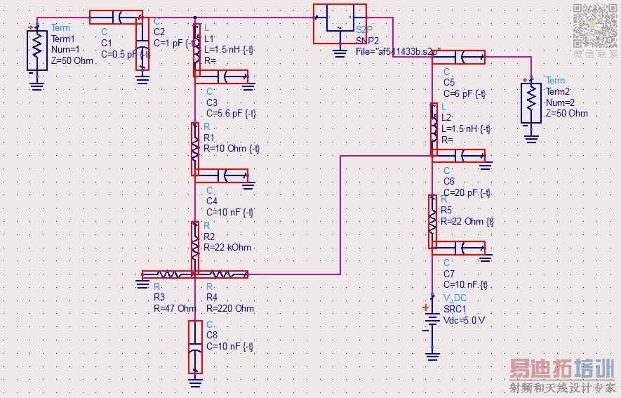
Hello again.
I need to simulate Tone-1 and Tone-2. But first in Tone-1 i get this warning. I couldn't find it.
Can you help me?
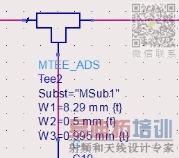
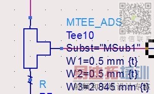

The text of the message tells you what the problem is: the geometry of your MTEE model is strange. The line widths are very different, and the electrical model for the MTEE is not designed for that extreme step in width. The MTEE model will not be accurate with these dimensions.
What can you do? Check if your layout looks correct. Usually, the MTEE line width are the same on both sides. If your case, they are very different. You can insert an MSTEP element to include the electrical effect of the step in width (from 8.29mm to 0.5mm).
1-DC simulation:OK
2-s-paramater simulation: OK
3-IIP3 & OIP3 simulation: Not OK
What is the wrong? I changed only RF freq. But it didn't work :(
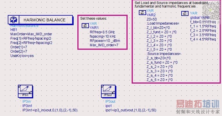

What is not OK. It is difficult to tell without knowing more about the simulated/expected results. The common mistake made when doing any intercept point measurement is to be using an input drive power level that is too high. To measure intercept point the amplifier should be driven in the linear region of operation. If it is driven into or close to saturation then the assumptions in the calculation will not be correct and the results will be inaccurate.
Dear RealAEL,
it means i could not simulate OIP3 and IIP3. Results have nothing seen at the attachment.
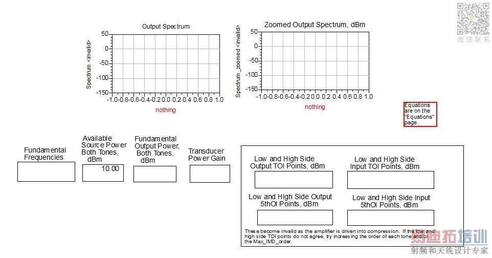
You have not defined "vout". You need to add a named net at the required point in the schematic to make that measurement.
thnx for ur advice.
Dear RealAEL.
I want to simulate P1dB and IP3s. First i tried to simulate P1DB point . But i got an error while typing eqn. What can be wrong?

You are trying to create an equation that is effectively Gain=Pout(dBm)-Pin(dBm)
1. dBm(Vout) is not a power measurement but a voltage measurement. Power is voltage x current.
2. Variables like RFPwr do not automatically get added to the dataset to be available in the Data Display to be able to use it in an expression. Edit the HB Controller Output Tab and add RFPwr to the list of Save by name variable values prior to simulation.
Dear RealAEL,
I follow this example http://edocs.soco.agilent.com/displa...ion+(ADS+only) with http://www.youtube.com/watch?v=sD7cVfQ9d2g . But when i enter eqn there's no HB1.HB.RFPwr. What can be the reason?
Thanks a lot.

Dear sir,
Really i have been trying for two weeks but i couldn't find what is wrong. i want to fiind P1dB point and then IP3 points. Please help.
document says gain=dBm(HB1.HB.Vout[1])-HB1.HB.Pin but there is no "HB1.HB.Pin" . what can i do?


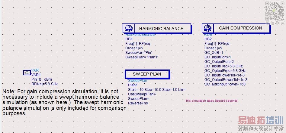
You have defined Pin using a variable. Variable data will not be included in the simulation dataset automatically. You need to add it to the saved data. Edit the HB simulation controller and on the Output tab select Add/Remove... button at the botton and Add Pin data to the Current Selection list. Re-run the simulation and the data should become available.
I have already done it :( But there is no "HB1.HB.Pin" . Are there any different way to measure P1dB point?
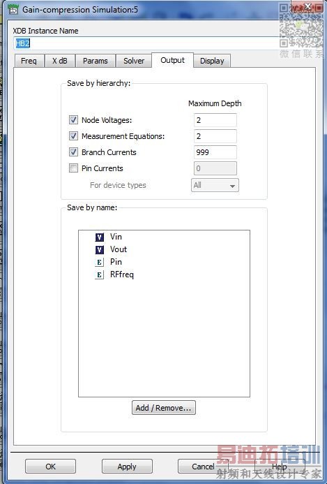

If yo are sure that the variable data is being written to the simulation dataset but you do not see the data when reading a dataset from the Data Display then the two are different. Do you have multiple datasets in the project? Are you sure you are looking at the correct dataset?
i tried all datasets.
Also i tried sample PA.dsn and i pushed my circuit in it. when i simuate it gave me -162dB S21 value :(
Dear husamsdu:
I aslo have an exercise about design LNA with parameters: f= 2,4 GHz, B = 200 MHz, G >= 20dB, NF<=2 dB by ADS. But this is my first time using this software. My computer was installed ADS 2011. Can you show me your design (by ADS format), I can facsimile my Ex follow on yours. Tks so much.
申明:网友回复良莠不齐,仅供参考。如需专业帮助,请学习易迪拓培训专家讲授的ADS视频培训课程。
上一篇:ADS 2009U1 vs ADS 2011: Frequency response shift problem
下一篇:Microstrip Transmission Line ADS
 国内最全面、最专业的Agilent ADS培训课程,可以帮助您从零开始,全面系统学习ADS设计应用【More..】
- Agilent ADS教学培训课程套装
- 两周学会ADS2011、ADS2013视频教程
- ADS2012、ADS2013射频电路设计详解
- ADS高低阻抗线微带滤波器设计培训教程
- ADS混频器仿真分析实例视频培训课程
- ADS Momentum电磁仿真设计视频课程
- ADS射频电路与通信系统设计高级培训
- ADS Layout和电磁仿真设计培训视频
- ADS Workspace and Simulators Training Course
- ADS Circuit Simulation Training Course
- ADS Layout and EM Simulation Training Course
- Agilent ADS 内部原版培训教材合集
