- 易迪拓培训,专注于微波、射频、天线设计工程师的培养
Finding P-1db and P-3dB in ADS
I want to find p1dB and P3dB in ADS for my LNA. Should I plot Pout and Pin in a figure and plot a straight line to find deviation? If I should do that, to see Pout and Pin I should use harmonic balance and a source in the input of the circuit? Cannot I use s-parameters simulation? Please help.
Yes, use Pout vs Pin with a variable power source at the input.
Use harmonic balance, and not linear S-parameter simulation, from the moment that those already measured the scattering parameters at specific input levels.
thank you vfone.
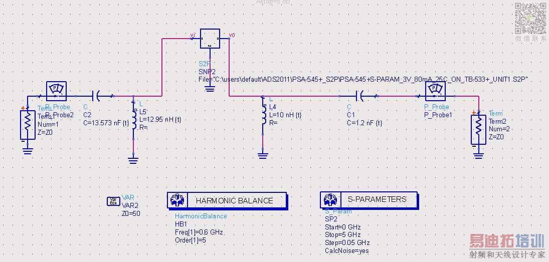
As you see my circuit in the figure, it is based on S-parameters and I do not have model of the transistor. So, I think I cannot use harmonic balance?!
Is there no other way to find P1db or P3db? For example by Power Gain which is available with S-Parameters simulation by this equation:
G=pwr_gain(S, Zs, Zl, Zref)

Sorry f_t, but it's not possible from a set of LINEAR parameters, you need some kind of a nonlinear model to simulate P1dB and so on.
I highly appreciate, johnjoe,
My professor has said that I have to find the amount of two LC filters to adjust P3dB at 0.7 GHz and 0.5GHz with center frequency 0.6Ghz for the circuit attached before. Now, because I cannot obtain P3dB (all parameters are linear), I can not obtain amounts of two filters. Is it true?
If you don't have the nonlinear model of the active device you cannot find any compression points, and also cannot find the values of the passive LC components in this matter.
You explain your problem with wrong definitions...
P3dB or P1dB definitions are different than you're looking for.These are nonlinear compression points and there is no relation between your problem and them..
You're looking for 3dB (1dB) bandpass filter "cut-off" frequencies.In order to do that, you should simply do a s-parameter simulation and then do what you want
Don't involve with nonlinear simulations..
Bigboss,
Thanks.
But, how should I find 3dB (1dB) bandpass filter "cut-off" frequencies by using S-parameters?
So as I understood, you want to design a lc-bandpass filter with center freq. 0.6 ghz and bandwidth(-3db) 0.2 ghz? Just have a look in a book about filter calculation, it's not so complicate. Or use ADS, it has a filter design tool, consider the manual and a simple standard filter is designed in 5 min. If you continue to design, you should also take some impedance matching into account.
It worked. It was a misconception about two similar names. P3dB for filter and P3dB for nonlinear amplifiers.
Thanks
申明:网友回复良莠不齐,仅供参考。如需专业帮助,请学习易迪拓培训专家讲授的ADS视频培训课程。
上一篇:Band Pass Filter Design for 2.4 -2.5 GHz by ADS tool
下一篇:Is Yaggi Udda Antenna simulation is possible on ADS MOMENTUM 2008?
 国内最全面、最专业的Agilent ADS培训课程,可以帮助您从零开始,全面系统学习ADS设计应用【More..】
- Agilent ADS教学培训课程套装
- 两周学会ADS2011、ADS2013视频教程
- ADS2012、ADS2013射频电路设计详解
- ADS高低阻抗线微带滤波器设计培训教程
- ADS混频器仿真分析实例视频培训课程
- ADS Momentum电磁仿真设计视频课程
- ADS射频电路与通信系统设计高级培训
- ADS Layout和电磁仿真设计培训视频
- ADS Workspace and Simulators Training Course
- ADS Circuit Simulation Training Course
- ADS Layout and EM Simulation Training Course
- Agilent ADS 内部原版培训教材合集
