- 易迪拓培训,专注于微波、射频、天线设计工程师的培养
Why big cell size leads to wrong results?
Here is example in attachment: S11 curve for 0.1x0.1 mm grid, and for 0.2x0.2 mm grid with strange spike to +15dBm. Why it happens?
Having done technical support for Sonnet, my answer is: It is very difficult to troubleshoot support cases without looking at the simulation files.
There is no general dependency between cell size and your strange unphysical results. Unphysical results (S11>0dB) in Sonnet are always caused by port de-embedding that breaks. Port de-embedding assumes that the calibration standards are single moded lines (e.g. double length = double phase). If we simulate a model where lines are overmoded, or if we have box modes, then the lines are no longer single mode and the de-embedding theory breaks and we might get funny results.
So there is no such direct dependency as you suggested. We would neeed to see the model to find the problem.
You was right, i tried to turn off de-embedding in setup and saw different result without spike. Now have feeling that using long lines to the box and putting usual port is better. Upload my sonnet project if still have problems.
I used this nice tutorial:
http://www.gunthard-kraus.de/Tutoria...l_Sonnet_e.pdf
they use autognd port directly on the patch (and calculate radiation edge resistance on page 17 from S11). I followed this tutorial, it worked nice until i changed laminate and patch size.
Here is one problem: i made two projects, almost identical, but center frequency differs too much. What's wrong with my setup?
Attached two projects, one gives 10.5 and another - 10.9 GHz.
p.s. Also i was able produce this huge difference with a smaller position shift, but project was altered too many times, so i can't find how i did it before =)
Gunthard had sent me his appnote for review before he published it, but I have to admit that I didn't check this detail enough. Looking at this "radiation resistance" aspect now, I'm very sceptical if this modelling approach is valid.
FR4 with the high permitivity and large thickness, combined with Sonnet's metal box walls, combined with the large box size, is a stress test for the port calibration method. There is a "forest" of box resonances in the frequency range of interest ...
By default, calibration lines are 1/2 box dimension (or reference shift length, if you have used reference shift) and twice of that. If there is any other propagating mode (box mode or higher order modes in the substrate or substrate), this will cause the port calibration to fail. Using the autogrounded ports means that you create a vertical current at the port location, and that might excite some higher order mode in the substrate that you don't excite with box wall ports.
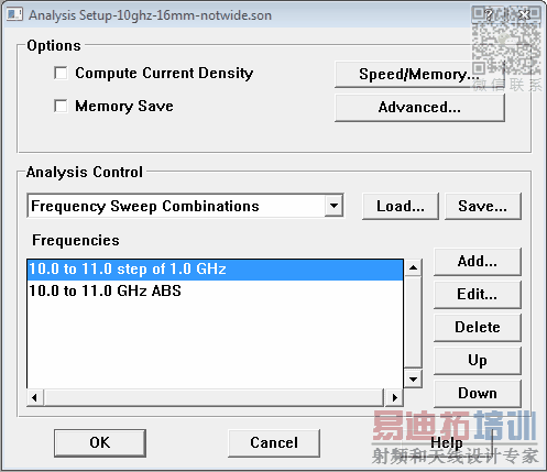
Actually, both simulation give both resonances, if we simulate with enough frequency samples. Your files are two of the very few cases where the adaptive sweep misses a resonance. You can help the adaptive sweep by adding a discrete sweep BEFORE the adaptive sweep, to make sure it doesn't miss something.

Then, you see that both models have both resonances (which might be antenna or box/substrate mode resonances).

Switching OFF port calibration isn"t a solution, because Sonnet needs port cal for accurate results for this setup.
One possible solution would be to make the box a little bit smaller, so that the box resonances move up in frequency. If you simulate the antenna with two box sizes that are 20% different, and the "antenna resonance" is still there, we can expect that it is a real antenna resonance. Otherwise, it might be not real (not real for the antenna) and just some box or substrate model that you have excited.
Another check for "fake" resonances from box/substrate modes is to change the feed. See attached model with autogrounded port. 10ghz-16mm-autogroundport.zip
All this is somewhat painful, as mentioned earlier in this post. Sonnet with its closed box simulation approach, and related calcibration issues, is limited when we want to analyze radiating structures in large boxes.
I changed patch sizes to 6.7mm x 6.7mm in your file and still get resonance at 10.5GHz =)
Yes, it is really a pain. But i still have hope.
申明:网友回复良莠不齐,仅供参考。如需专业帮助,请学习易迪拓培训专家讲授的ADS视频培训课程。
上一篇:why directivity is larger than gain in ADS
下一篇:uwb wilkinson power divider using ads
 国内最全面、最专业的Agilent ADS培训课程,可以帮助您从零开始,全面系统学习ADS设计应用【More..】
- Agilent ADS教学培训课程套装
- 两周学会ADS2011、ADS2013视频教程
- ADS2012、ADS2013射频电路设计详解
- ADS高低阻抗线微带滤波器设计培训教程
- ADS混频器仿真分析实例视频培训课程
- ADS Momentum电磁仿真设计视频课程
- ADS射频电路与通信系统设计高级培训
- ADS Layout和电磁仿真设计培训视频
- ADS Workspace and Simulators Training Course
- ADS Circuit Simulation Training Course
- ADS Layout and EM Simulation Training Course
- Agilent ADS 内部原版培训教材合集
