- 易迪拓培训,专注于微波、射频、天线设计工程师的培养
Input impedance over a frequency range in ADS
I am simulating a network given in a book using ADS.I have to plot the input impedance over a frequncy range.
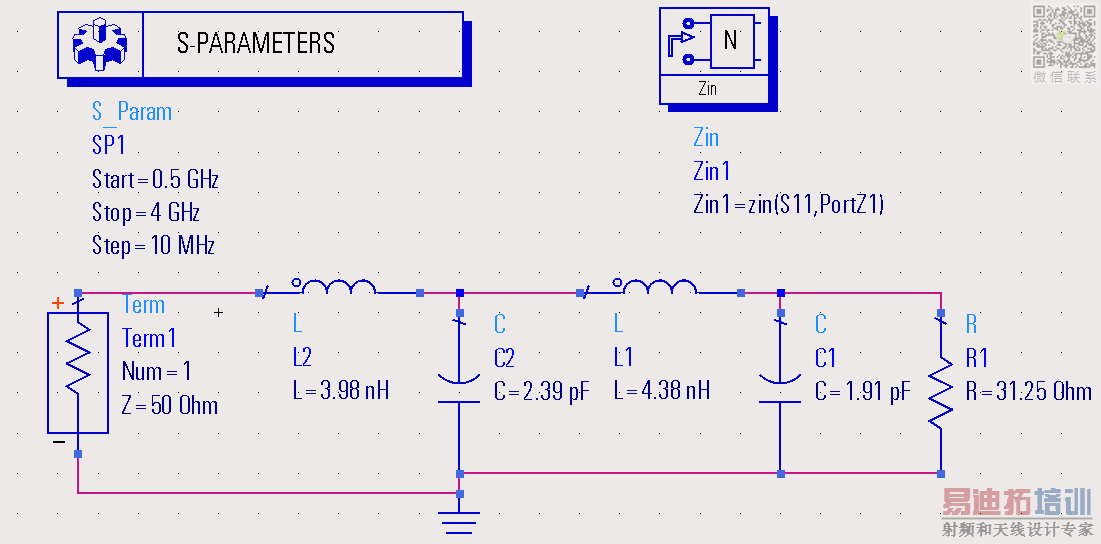
See the following setup to I created do that:
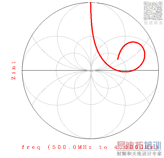
I am getting following result:
Kindly help me with following two questions:
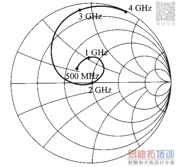
(1) What to do so that it resembles with the answer given in the book (hopefully that is correct!), see below

( why ads is showing smith chart from four directions)
(2) could you kindly explain the arguements used in Zin block? I learned it in some tutorial to add zin block but I couldn't find any explanation thereof.
Thanks.
Zin is not equal to S11..
At first graph, you drawn Zin and Zin is outside of Smith Chart.
But at second one, S11 has been drawn on Smtih Chart therefore you see the difference.
If you draw S11 on Smith Chart, you will see the same curve.
Zin block calculates Input Impedance by aid of s-parameters of circuit.
Zin=Zo[(1+S11)/(1-S11)]
BigBoss, Thank you very much for your reply. In RFCD book by Ludwig/Bogdanov, at pn-133 this plot (2nd figure) appears. They claim it to be Zin. So I should consider that wrong.
Couple of more questions-
In the first figure, when I put marker at 2GHz, It gives Zin1=49.774/-0.077, impedance=-52.050-j0.003. Hand calculaton says it should be around 50ohm. So it looks Ok.
What is that -0.077 in Zin1? Phase, right?
About Zin block, ads help says
"Given a reflection coefficient and the reference impedance, this measurement returns the input impedance looking into the measurement ports
Syntax
z = zin(Sii, Z) ".
But in my setup PortZ1 comes as default in argument when I draged & dropped Zin block. Is PortZ1=term impedance?
It appears to me that I can use this Zin block to find output impedance, too. If yes, what should be the syntax? z=zin(S22,PortZ2) ?
Yes, imaginary part of Impedance in complex form.
Yes, if you have 2 or more ports, all you should have to define port index and Reference Characteristic impedance of this port.
I tried to use this formula in my Qucs project but it doesn't work correctly. What is my mistake? On bottom you can find comparison with ADS simulation. Please, advise me how to find the input impedance of this quarter-wavelength transmition line using S or Z parameters?

Look at carefully to the formulae, there isn't "mag" definition.
Zin is a "complex" impedance so that it's got real and imaginary part.At the first equation you have taken "mag" of S11 that is wrong and then you took again mag of Z11 that is also wrong.
implement the formulae correctly and you will see real and imaginary parts of the input impedance.
申明:网友回复良莠不齐,仅供参考。如需专业帮助,请学习易迪拓培训专家讲授的ADS视频培训课程。
上一篇:ADS Tutorial for Polyphase Filter
下一篇:warning message in ads (snap distance)
 国内最全面、最专业的Agilent ADS培训课程,可以帮助您从零开始,全面系统学习ADS设计应用【More..】
- Agilent ADS教学培训课程套装
- 两周学会ADS2011、ADS2013视频教程
- ADS2012、ADS2013射频电路设计详解
- ADS高低阻抗线微带滤波器设计培训教程
- ADS混频器仿真分析实例视频培训课程
- ADS Momentum电磁仿真设计视频课程
- ADS射频电路与通信系统设计高级培训
- ADS Layout和电磁仿真设计培训视频
- ADS Workspace and Simulators Training Course
- ADS Circuit Simulation Training Course
- ADS Layout and EM Simulation Training Course
- Agilent ADS 内部原版培训教材合集


