- 易迪拓培训,专注于微波、射频、天线设计工程师的培养
design inductors with ADS
录入:edatop.com 点击:
Hello
I m lookinf for examples of the design of inductors with ADS,
Thank you very much for your help
I m lookinf for examples of the design of inductors with ADS,
Thank you very much for your help
It depends on your technology and frequency. Should it be on a pcb or on chip?
I want to design an inductor On a Pcb (printed inductor)
ok, and frequency range?
Let's say 125 Khz like the one used foe receivers in wireless power transfer
http://www.tdk.co.jp/wireless_e/pdf/...-15f5-g_en.pdf
forget about printed inductors at this frequency because you need a lot of area. what is the purpose of the inductor? some power transfer or filtering?
Some power transfer
it's much easier to buy a coil instead of designing one, especially at such low frequency. If you really want a printed ind. you're faced with different problems, e.g. between traces you have to use a minimum spacing or the thin trace thickness. IMHO, it's not a good idea.
For Coil that I found in internet , they have a mean dimension 3cm x 4 cm for my application I need a coil with a max dimension of 4 cm x 2 cm
Maybe you know some references of smaller coils?
Maybe this one: http://www.farnell.com/datasheets/1782026.pdf . it's around 3x3, but a printed ind would be for sure larger with same inductance value.
the inductance value can be changed , the design chracteristics are :
Nevertheless, take a commercial one, because you can't choose your inductance too small for an adequate power transfer. OR make your own one from copper wires, also possible.
Inductor mechanical dimensions are theoretically ( and surely up to moderate RF frequencies ) almost independent from the frequency.
For instance 1uH@100kHz has always same dimension @1MHz
or 1nH@100MHz has dimensions as same as @1GHz..
For an information only...
Agree, but comparing his idea of a pcb inductance with a commercial one, the pcb ind. will be larger for the same value.
10x for your answers ; I think that I'll test the both: commercial coil and the same time I want to learn how to simulate coils with ADS for future applications
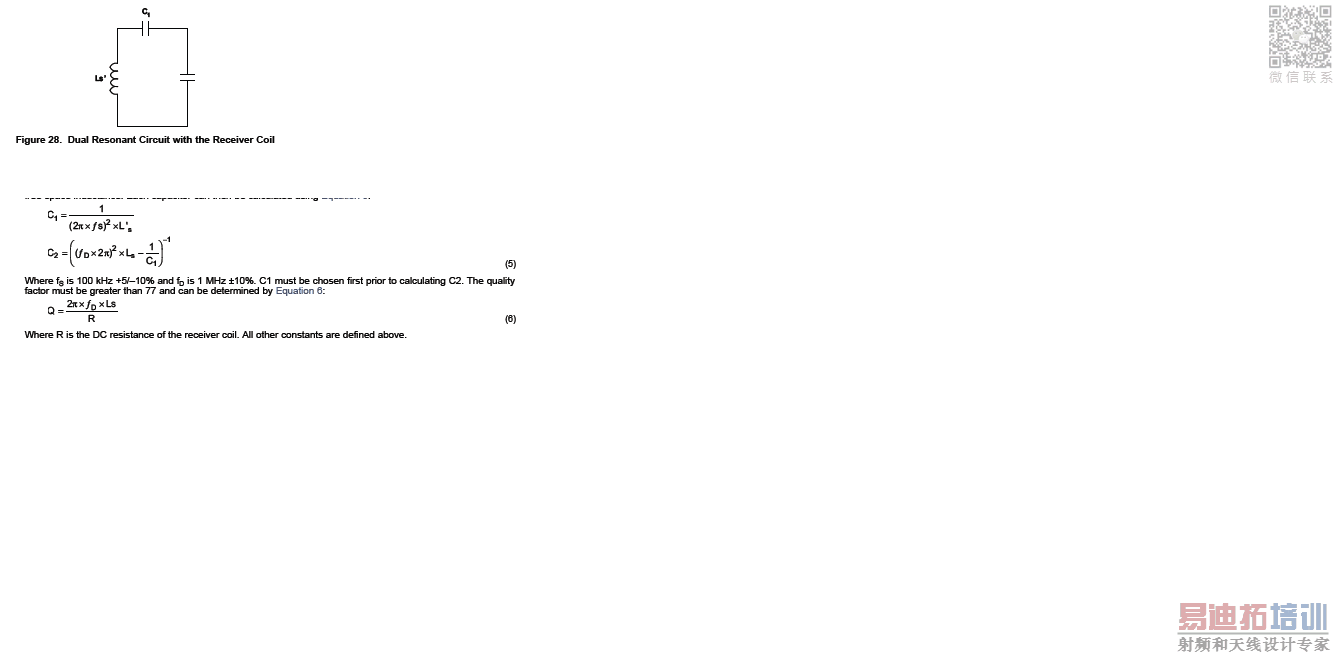
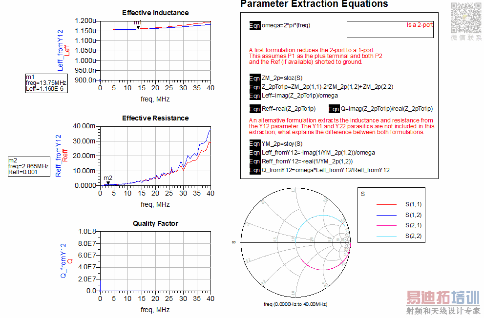
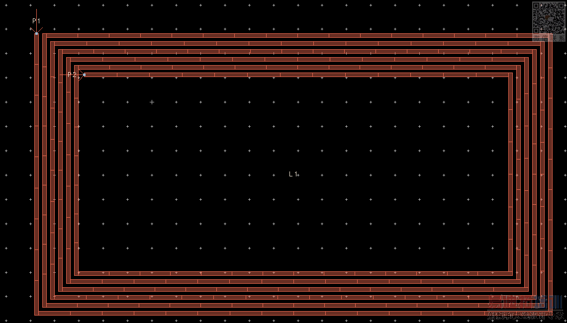
so, I tried to simulate a commercial coil with ADS after simulation , we can insert a template that calculate directely L, R and Q:
with my design I get the same value of L =1.18 uH but not for the resistance that is very low which give a very high Q
please have you any idea? any explinations? why I don't get the right value of R?
http://www.abracon.com/NFC-antenna/ANFCA-2515-A02.pdf
How you simulated your design? Maybe you can also post your pcb stackup for em-simulation.
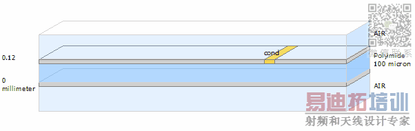
Is your cond material PEC?
I used copper
Mhmm, can you upload your simulation, that I can check?
申明:网友回复良莠不齐,仅供参考。如需专业帮助,请学习易迪拓培训专家讲授的ADS视频培训课程。
上一篇:simulating mixer return losses in ADS
下一篇:Regarding Series Stub Matching in ADS
ADS培训课程推荐详情>>
 国内最全面、最专业的Agilent ADS培训课程,可以帮助您从零开始,全面系统学习ADS设计应用【More..】
- Agilent ADS教学培训课程套装
- 两周学会ADS2011、ADS2013视频教程
- ADS2012、ADS2013射频电路设计详解
- ADS高低阻抗线微带滤波器设计培训教程
- ADS混频器仿真分析实例视频培训课程
- ADS Momentum电磁仿真设计视频课程
- ADS射频电路与通信系统设计高级培训
- ADS Layout和电磁仿真设计培训视频
- ADS Workspace and Simulators Training Course
- ADS Circuit Simulation Training Course
- ADS Layout and EM Simulation Training Course
- Agilent ADS 内部原版培训教材合集