- 易迪拓培训,专注于微波、射频、天线设计工程师的培养
problem with 180 hybride coupler in ADS ?
录入:edatop.com 点击:
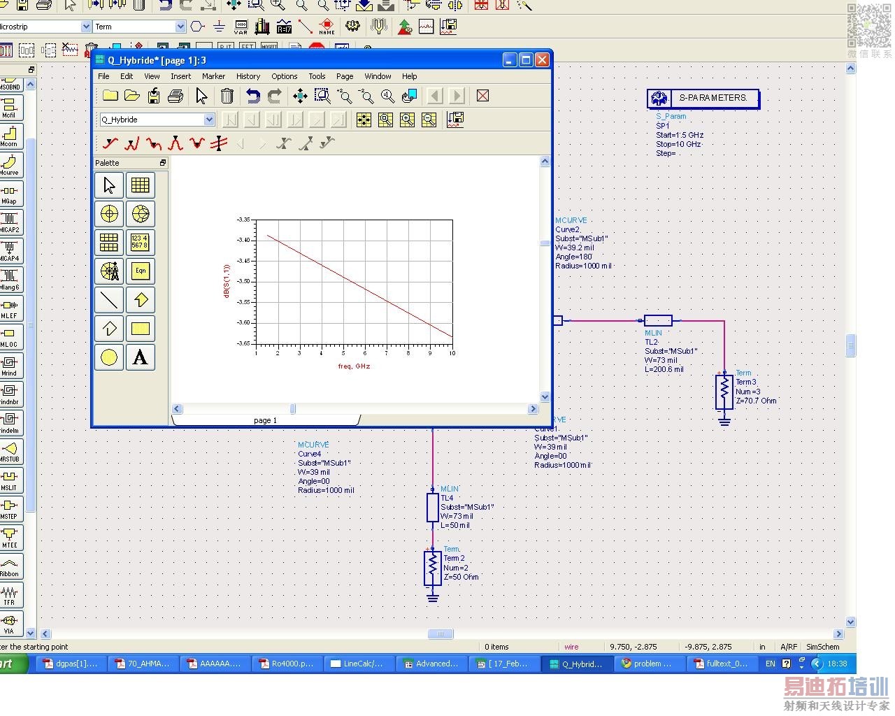
Im designing a 180 Hybride coupler http://images.elektroda.net/15_1303837015.jpg
but this design im doing just taken from one project from the internet in ADS the out put i have is totally different .plz can any body check this one
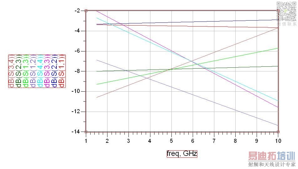
this is the output I got which totally wrong
I did not understand this one "1-check your ports u should have VSWR something between 1.4-1.027"
and what is the impedance of the circle
thanks
. I will try to change the impedance for ports now . I want to have a center frequency at 3 GHz but I dun know how to do it in ADS
---------- Post added at 09:48 ---------- Previous post was at 09:43 ----------
may you check the angles I used in curve whether they maybe Not correct ?
but this design im doing just taken from one project from the internet in ADS the out put i have is totally different .plz can any body check this one
please indicate the impedances and the output and input arms I mean the impedance for each stub in your design so I may check for u
z= 50 ohm
---------- Post added at 18:36 ---------- Previous post was at 18:35 ----------
70.7 ohm
---------- Post added at 18:41 ---------- Previous post was at 18:36 ----------
this is the output I got which totally wrong
send me your other S parameters and check your substarte definistion think it is not the design mostly it is the way you defined the design and make the length of the outouts all L=50mil for all outputs later you can convert to 200mil if you wnat

1-check your ports u should have VSWR something between 1.4-1.027
2-send me the pic of the other S parameters
3-Chang your design by changing only the impedances of the circle if you have the same results then definitely it is a matter of definitions in design

I did not understand this one "1-check your ports u should have VSWR something between 1.4-1.027"
and what is the impedance of the circle
thanks
i ment check you input and output ports are they correct
I ment instead of putting 70 ohm make it another number for all the four stabs and the bends (Tee 1 tee2 tee3 tee4 qadn curve 1 curve 2 curve 3 curve 4)but do not change the output ports impedance and see will there be any difference
and send me your S22 S33 S44 S12 S13 S23 S34 to see are they the same in error
what is your center frequency and the expected frequency range of the ratrace devider you are designing?
. I will try to change the impedance for ports now . I want to have a center frequency at 3 GHz but I dun know how to do it in ADS
---------- Post added at 09:48 ---------- Previous post was at 09:43 ----------
may you check the angles I used in curve whether they maybe Not correct ?
can u please make the pic high resolution it is not clear for me
CHECK IT plz , plz keep in mind im new
check curve 3 it has W=39.2 it should be 39 but the angle is 180 and the other curves are 00 angle .....
but the angle is 180 and the other curves are 00 angle ..? the angel of others curves should be zero or not
It should be all symetrical you can check by veiewing the layout if it is symetrical,
this is the layout ,
So you have one half of the circle correct and the other half wrong, means the half circle you are seeing in the layout you should make another correct half on the other side
and also the outputs and inputs terminals have wrong positions but now only correct the circle because the ports might be wright if you make the other half fo the circle correct
so check the half circle that appears in the layout corresponds to which curve you have in the schematice and then make the other two in the same way, think the wrong two are because of the angles if the correct two curves correspond to the 00 and 180 any way check
what about this Now~?
may u tell me when I simulate the layout i have this red boxes I already circle and boxed them . may u tell me what is that meant
what is the simulation output now do have any output?
I did not work on this software so check if you have a place that gives you an error report or some thing like that
I have no error at all ,however, the result still the same
申明:网友回复良莠不齐,仅供参考。如需专业帮助,请学习易迪拓培训专家讲授的ADS视频培训课程。
上一篇:ADS Momentum simulation with varactor?
下一篇:Need of ADS software
ADS培训课程推荐详情>>
 国内最全面、最专业的Agilent ADS培训课程,可以帮助您从零开始,全面系统学习ADS设计应用【More..】
- Agilent ADS教学培训课程套装
- 两周学会ADS2011、ADS2013视频教程
- ADS2012、ADS2013射频电路设计详解
- ADS高低阻抗线微带滤波器设计培训教程
- ADS混频器仿真分析实例视频培训课程
- ADS Momentum电磁仿真设计视频课程
- ADS射频电路与通信系统设计高级培训
- ADS Layout和电磁仿真设计培训视频
- ADS Workspace and Simulators Training Course
- ADS Circuit Simulation Training Course
- ADS Layout and EM Simulation Training Course
- Agilent ADS 内部原版培训教材合集