- 易迪拓培训,专注于微波、射频、天线设计工程师的培养
How Do I Change Length Units In the AWRDE and Check For Any Resulting Errors in Layout
What should I do if I started designing my schematics using inconvenient length units and I want to change them now?
Please review New Design Considerations in the online help (AWRDE User Guide > AppendixB). Among the important pre-design considerations listed, is the setting of units.
Length Parameters Set to Numerical Values
If your schematics do not include equations and variables to specify physical dimensions, follow this procedure to change your project's length units and ensure the change does not cause any problems:
Go to Options > Project Options... and change the Length type to your desired units.
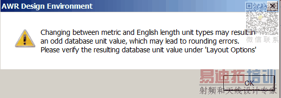
Click OK to dismiss the warning box shown below.

Go to Options > Layout Options... and if necessary round off the Grid Spacing and the Database Unit Size to desired values.
In your schematics, check all element parameters with length units (e.g. W and L on microstrip lines), and make sure they are rounded correctly. The full precision parameter values are only visible when they are being edited. So in schematics, you must double-click on parameters, or on the elements to see the parameters' exact (not rounded) values.
Open each schematic's layout view and if there are missing components, go to Layout > Regenerate Layout to re-generate your layout. Re-generating your layout is likely to re-arrange the cells. Make sure the cells in the layout are still connected properly. Use the Edit > Snap Together command to re-attach any components that were disconnected as a result of the changes so far.
Length Parameters Set to Variables
Generally, equations are unaffected by project units. This will cause elements whose dimensions are set by variables or equations to expand or contract in unexpected ways.
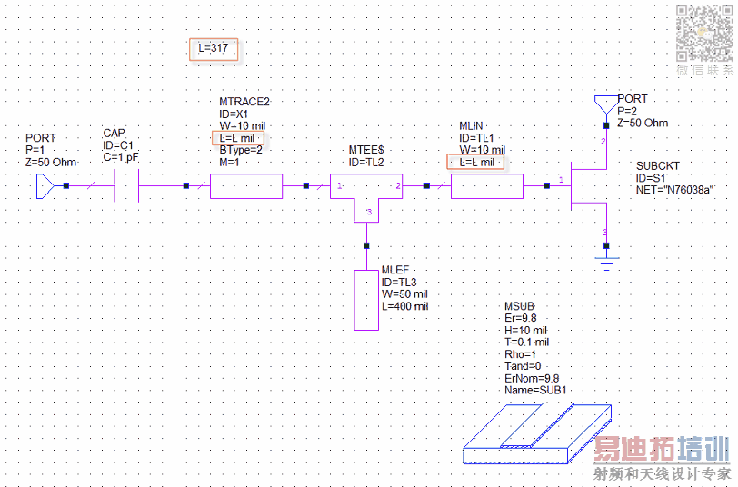
The following figure shows a schematic in which the length of some of the elements is set by the variable "L", whose value is assigned in an equation. As you can see the length units are mils.

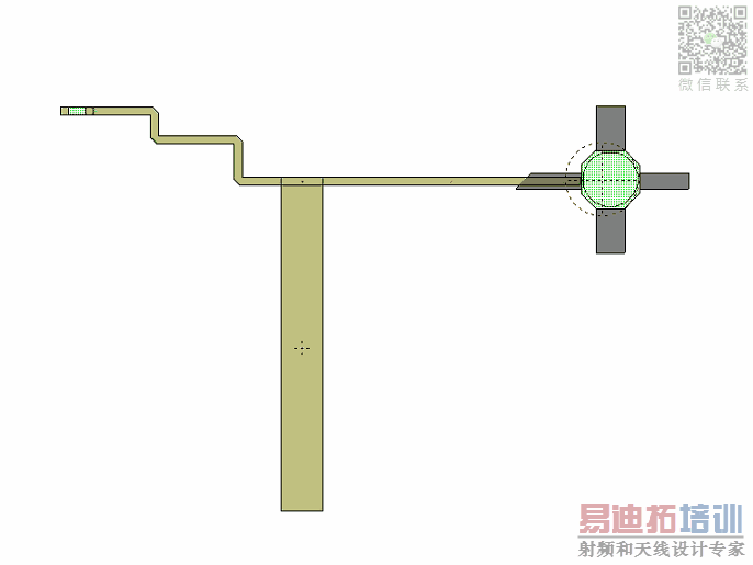
The layout of the above schematic before the length units are changed is shown in the following figure.

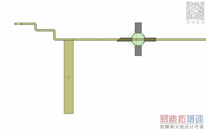
The layout of the above schematic after changing units from mil to mm is shown in the following figure.

As shown above, the size of the elements that use variable "L" changes when length units change. Convert your equations' numeric values to counter the unit change.
Note: Changing length units will not affect the elements, if Dependent parameters use base units is selected in the schematic options.
To access Dependent parameters use base units checkbox, right click on your schematic file in Project pane and go to Options > Schematic tab.
With the Dependent parameters use base units selected, length units for parameters defined by variables or equations will be in meters. Make sure you calculate your equations accordingly.

AWR Microwave Office 培训课程套装,视频教学,帮助您快速学习掌握MWO...
上一篇:How to Add Text to MMIC Layouts in PDKs to be DRC(Design Rule Checking) compliant
下一篇:How Can I Fix the Shorted Circuit Created in Spiral Inductors Between the Bridge and the Outermost Segment
 Microwave office专业系统的视频培训套装,帮助您从零开始,全面学习MWO的设计应用【More..】
频道总排行
- Which CPW Line Models Support
- Problem Saving Layout Rulers in
- Calculate 3dB Bandwidth of Band
- AWR&'s GERBER File Format Details
- Using DXF Format with the AWR
- DXF Files Do Not Open in AutoCAD
- FAQ: Using Encrypted HSPICE Netlists
- Touchstone File Repair Utility
- How Can I Fix the Shorted Cir
- Failure initializing the AWR Sc
