- 易迪拓培训,专注于微波、射频、天线设计工程师的培养
EMSight Proximity to Enclosure Issues
How much space do I need between the conductors and the sidewalls in an EM structure?
This article describes a simple method for determining the appropriate spacing between the sidewalls of an EM structure and the conductors.
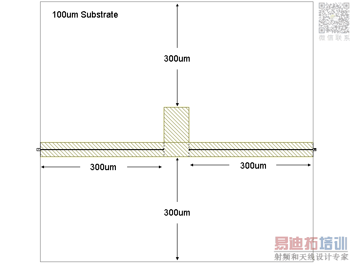
EMSight models the structure sidewalls as perfect conductors, so placing a conductor nearby will add shunt capacitance. Therefore, you will want to make your structure large enough to include the conductors you are trying to simulate, plus two or three substrate heights of space between each wall and the conductors. (Please see attached picture below).

To be sure you have enough space, you might want to set up a simplified version of your structure. Use the same substrates, but reduce the grid resolution, and draw a single conductor about 1/4 wavelength long at your highest frequency of interest (Fhi). One side of the conductor should attach to the wall, where you will connect a port, and the other side should stop 1 substrate height short of the far wall. Set the structure to simulate at Fhi. Now, you can run multiple simulations of the structure quickly, increasing the box size each time to have more and more distance between the open end of the conductor and the wall. When the magnitude and angle of S11 change less than the desired amount, you have found the minimum wall spacing for your structure.
AWR Microwave Office 培训课程套装,视频教学,帮助您快速学习掌握MWO...
上一篇:Emulating Standard Cadence Bindkeys in AWR
下一篇:DXF Files Do Not Open in AutoCAD
 Microwave office专业系统的视频培训套装,帮助您从零开始,全面学习MWO的设计应用【More..】
频道总排行
- Which CPW Line Models Support
- Problem Saving Layout Rulers in
- Calculate 3dB Bandwidth of Band
- AWR&'s GERBER File Format Details
- Using DXF Format with the AWR
- DXF Files Do Not Open in AutoCAD
- FAQ: Using Encrypted HSPICE Netlists
- Touchstone File Repair Utility
- How Can I Fix the Shorted Cir
- Failure initializing the AWR Sc
