- 易迪拓培训,专注于微波、射频、天线设计工程师的培养
How Do I Fix My Layout If I Can No Longer View It or I Only See the Ratlines
What should I do if I no longer see my layout or I only see ratlines, and the "autosnap" tool does not snap the layout cells together?
Solution
Changes In Length Units
Changing a projects global length units might cause layout problems for certain schematics. In order to solve layout problems caused this, please read the article on changing the length units .
Large Parameters
The most common mistake that causes layouts to be too large and out of proportion is using unintentionally large values for one or more dimensional parameters; e.g. the length of a microstrip line.
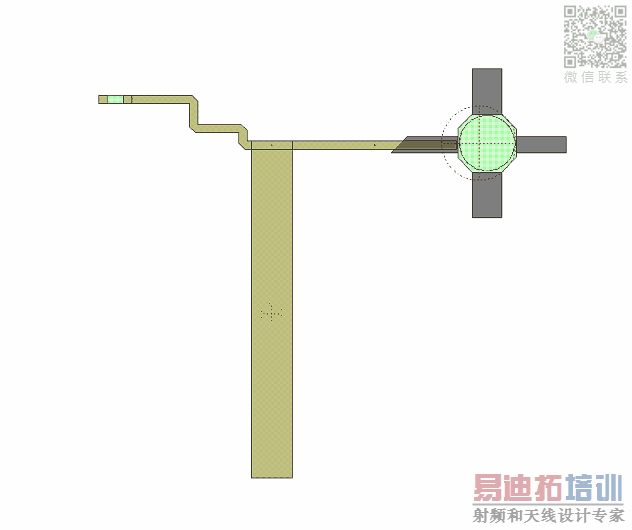
As shown in the figure below, the layout view of a schematic may look like a long ratline and a small shape at one or both ends.

The long ratline is an element with a very large width or height and the small shape on the left consists of the other elements in the schematic.
The schematic is shown in the figure below, with the large parameter value highlighted.

To find your abnormally large elements and correct their size, follow the steps described below:
Go to View > Variable Browser.
Click on the Value column header twice to sort the elements by value from the largest to the smallest.
Correct the values as necessary.
Go to the layout view again, and select View > View All from the menu.
If your layout is still not visible, try the following, but note that these steps will re-arrange your elements:
Select all of your elements in the layout view using Ctrl + A, then select Edit > Snap Together.
If elements do not snap together properly, go to Layout > Re-Generate Layout to re-generate your layout. Then use the Snap Together tool again.
If after fixing large values and re-generating your layout, the ratline stays, your schematic might have additional issues other than large parameter values.
The example layout was corrected following the above steps, and is shown in the figure below.

AWR Microwave Office 培训课程套装,视频教学,帮助您快速学习掌握MWO...
上一篇:How Do I Make AWRDE Transformers (XFMR, XFMRTAP and XFMRTAP2) Not Transform DC
下一篇:How Do I Combine Load Pull Files
 Microwave office专业系统的视频培训套装,帮助您从零开始,全面学习MWO的设计应用【More..】
频道总排行
- Which CPW Line Models Support
- Problem Saving Layout Rulers in
- Calculate 3dB Bandwidth of Band
- AWR&'s GERBER File Format Details
- Using DXF Format with the AWR
- DXF Files Do Not Open in AutoCAD
- FAQ: Using Encrypted HSPICE Netlists
- Touchstone File Repair Utility
- How Can I Fix the Shorted Cir
- Failure initializing the AWR Sc
