- 易迪拓培训,专注于微波、射频、天线设计工程师的培养
HFSS15: Example that Uses Near Field Links
The figure below shows a horn antenna that will be linked to a target disk where the source will be included inside of the target.
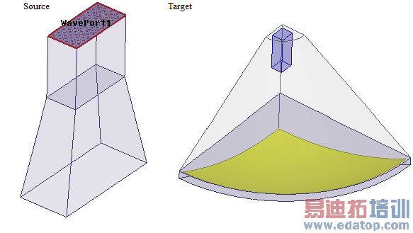
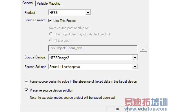
On the Incident Wave Source : Near Field Wave Options dialog box, the options shown in the figure below are checked owing to which the source is included in the target design.

The Near Field Setup Link settings are as shown in the figure below.
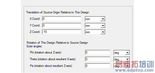
In the example of the horn antenna linking to a target dish, the co-ordinate systems of the source and the target coincide. You can use the X Coord, Y Coord, and Z Coord fields to set the source co-ordinate system. For instance if you want to move the source and its co-ordinate system closer to the dish by 15 mm you can enter -15 mm in the Z Coord field as shown below.
The 3D polar plot with the values of directivity for the source project (the standalone horn antenna withougt the dish) is shown below.
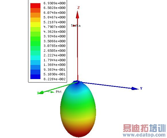
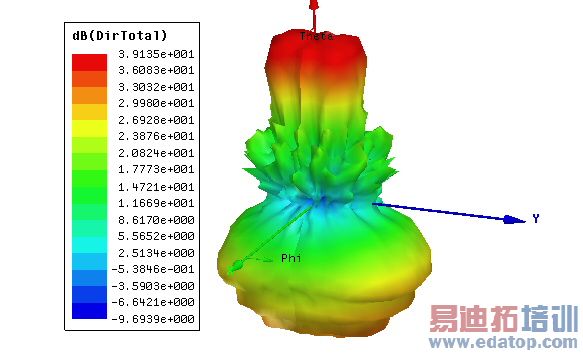
Then, when we apply the fields to the Target project with the dish, we get the values of the directivity shown in the figure below.
Note: The standalone horn antenna without the dish radiates in the negative Z direction while the target project which includes the dish antenna, radiates in the positive Z-direction. The 3D polar plot with the values of directivity after the application of the Near Field link is shown in the figure below.
HFSS 学习培训课程套装,专家讲解,视频教学,帮助您全面系统地学习掌握HFSS
上一篇:Example of Removing a Host Dependent User Option Setting
下一篇:Example of Terminals


