- 易迪拓培训,专注于微波、射频、天线设计工程师的培养
HFSS15: Lumped RLC Boundaries
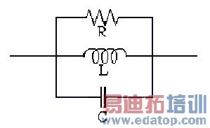
To model any combination of lumped resistor, inductor, and/or capacitor in parallel on a surface, create a lumped RLC boundary. A lumped RLC boundary represents R, L, and C in parallel:

Similar to impedance boundaries, the following condition holds at lumped RLC boundaries:
|
| (1) |
where
• ![]()
![]()
![]() is the is the unit vector that is normal to the surface.
is the is the unit vector that is normal to the surface.
• Etan ![]() is the component of the E-field that is tangential to the surface.
is the component of the E-field that is tangential to the surface.
• Htan ![]() is the component of the H-field that is tangential to the surface.
is the component of the H-field that is tangential to the surface.
• Zs ![]() is the surface impedance of the boundary, Rs + jXs, where
is the surface impedance of the boundary, Rs + jXs, where
• Rs ![]() is the resistance in ohms/square.
is the resistance in ohms/square.
• Xs ![]() is the reactance in ohms/square.
is the reactance in ohms/square.
Unlike impedance boundaries, you are not required to supply the impedance per square, but you must supply the actual values for R, L, and C. HFSS then determines the impedance per square of the lumped RLC boundary at any frequency.
A Fast frequency sweep is supported for this boundary condition.


