- 易迪拓培训,专注于微波、射频、天线设计工程师的培养
HFSS15: Mode Polarity
When HFSS computes an excitation mode pattern, the direction of the field at wt = 0 is arbitrary; the field can point in one of at least two directions. This document addresses how to remove the ambiguity of the field direction when a mode is not part of a set of degenerate modes. For the case of degenerate modes, there is no unique mode alignment and this topic is addressed in Mode Alignment.
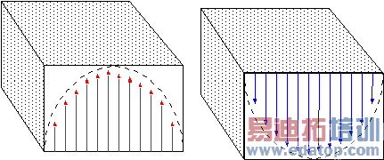
In the figure below, at wt = 0 the electric field pattern of the mode can point either up (left image) or down (right image). Either direction is correct - unless a preferred direction is specified. This issue becomes of concern when inspecting the phase angle of S-parameters.
For example, consider a 3D model containing two single-mode ports of the type shown in the figure. The phase of the computed S-parameters linking the two ports will flip by 180 degrees if the polarity of the mode at either port is reversed. Therefore when transmission S-parameter phase is of interest in models such as this, the user has the responsibility to properly set the mode polarity at each port.

To specify the polarity of a mode, a mode calibration must be performed by creating an appropriate integration line. For instance, if the preferred direction is up then the integration line should be drawn at the center of the waveguide starting at the bottom and ending at the top. In general, a mode calibration is automatically performed if an integration line has been defined for a mode where HFSS ensures that the real part of the line integral of the electric field of that mode is positive.


