- 易迪拓培训,专注于微波、射频、天线设计工程师的培养
HFSS15: Setting the Field Pattern Direction
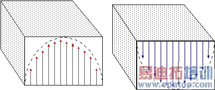
When HFSS computes the excitation field pattern at a port, the direction of the field at wt = 0 is arbitrary; the field can always point in one of at least two directions.
In the figure below, the mode 1 field at wt = 0 can either point to the left or to the right. Either direction is correct — unless a preferred direction is specified. To specify a direction, you must calibrate the port relative to some reference orientation by defining an integration line.

In the case of rectangular waveguides, visualize the difference in terms of a physical connection. If the up side of a port is aligned with the up side of the waveguide carrying the excitation signal, the signal at the port is in phase with what is expected. But if the up side of the port is connected to the down side of the waveguide, the incoming signal will be out of phase with the expected signal. Likewise, it is desirable to define which way is up at all ports on a structure; otherwise, the resulting S-parameters can be shifted from the expected orientation.
Calibrate a port to define a preferred direction at each port relative to other ports having identical or similar cross-sections. In this way, the results of laboratory measurements, in which the setup is calibrated by removing the structure and connecting two ports together, can be duplicated.
Note | Because integration lines can determine the phase of the excitation signal and traveling wave, they are ignored by HFSS when a ports-only solution is requested. |
HFSS 学习培训课程套装,专家讲解,视频教学,帮助您全面系统地学习掌握HFSS
上一篇:Setting the Curved Surface Visualization
下一篇:Setting the Maximum Delta Frequency Per Pass


