- 易迪拓培训,专注于微波、射频、天线设计工程师的培养
HFSS15: Setting up a Far-Field Infinite Sphere
To evaluate radiated fields in the far-field region, you must set up an infinite sphere that surrounds the radiating object. To plot far-field values across the sphere, you will select the sphere object from the Geometry list in the Traces dialog box when you create a report.
1. Click HFSS or HFSS-IE>Radiation>Insert Far Field Setup>Infinite Sphere.
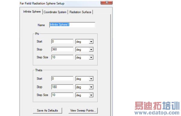
The Far Field Radiation Sphere Setup window appears.

2. Use the Sphere tab define the Name, Radius, and sampling of Phi and Theta for the near-field sphere. The radius is measured from the origin of the sphere’s coordinate system, which you specify under the Coordinate System tab. You can assign a variable to the radius, and a post-processing variable will often make sense in this context.
Specify the sphere’s sampling in terms of Start, Stop, and Step Size angles given in radians or degrees. To verify your settings, use the View Sweep Points button to display a list of the theta and phi sweep points. See Spherical Cross-Sections in the Technical Notes for guidelines for setting phi and theta.
You can use Save as Defaults to set the current values as the default for new near-field sphere setups.
3. Use the Coordinate Systems tab to specify the orientation of the sphere.
Use global coordinate system is selected by default, but in some cases the orientation of the antenna requires the use of a local coordinate system. In this case, select Use local coordinate system, and choose a local coordinate system that you created previously in the modeler.
4. Use the Radiation Surface tab to select the solved surface from which to calculate radiated fields.
Use Boundary Radiation Surfaces is selected by default, indicating that the radiated fields will be calculated using the assigned radiation or PML surface. For some models you may find it it more efficient and/or accurate to use an interior surface. In this case, select Use Custom Radiation Surface, and choose a face list that you previously created in the modeler.
Note | Do not use a sheet-object based face list as the radiation computation surface. |
You can use the Save as Default to set the current values as a default, and the Use Defaults button to use previously saved options.
Note | You must have defined at least one radiation or PML boundary in the design for HFSS to compute far-field quantities, regardless of which radiation surfaces you instruct HFSS to use when calculating the far fields. You do not need to re-solve the problem if you modify radiation surfaces in the Far Field Radiation Sphere Setup window. |
HFSS 学习培训课程套装,专家讲解,视频教学,帮助您全面系统地学习掌握HFSS
上一篇:Setting up HFSS and Running Distributed Memory Solutions
下一篇:Shortcut Menus in the History Tree


