- 易迪拓培训,专注于微波、射频、天线设计工程师的培养
如何在feko里面模拟端口馈电
幸好,FEKO从5.1起,加入了波导端口馈电功能(用AW卡实现)
此前,大都只能用加偶极子方式来等效一个端口模式,很复杂
具体用法参考example guide:example 8(方波导端口激励)
example 34(同轴线端口激励)

但AW卡目前还有几点限制:
1、只能在editfeko中设置
2、只能模拟方波导、圆波导、同轴线集中规则形式,不能模拟包括带状线在内的任意端面结构
3、同轴线内不能填充与背景介质不同的介质;
4、不能用于PO+MOM混合算法;MLFMM没有验证,
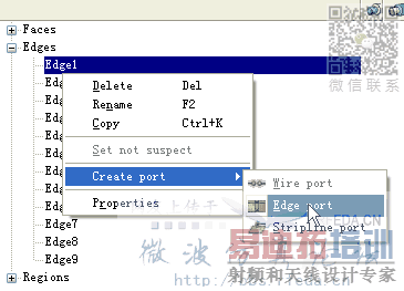
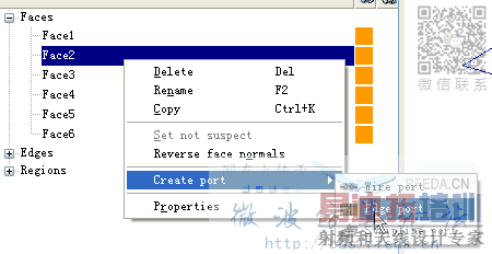
实际上,CADFEKO中也能方便地模拟一些常见的馈电结构,可以在任意相邻边上加端口(模拟微带线、带状线等结构),典型例子是Vivaldi天线,根据本人的经验,计算得到的VSWR等参数还比较准确


在此抛砖引于,希望大家在实用过程中发现问题,探索到更好的办法!
做做试验 赚点金币
呵呵!
修改为0金币出售---论坛不想像52RD那样,出售贴太多容易导致没有价值的贴子也被人拿来卖(您的这个贴肯定不止您出售的这个价值).
所有原创都会由小编直接加金币(数值肯定不会少于出售的价值),特别优秀的加威望给以鼓励.
希望大家都向 newtec 学习,多发原创!
另+20币.+1威望!
谢谢老总
同意免费提供 呵呵
希望大家多交流一下
能具体讲一下aw各项参数的设置含意么?
能具体说说怎么设置端口么
AW卡的使用也有很多不明白的地方,如设置TM/TE11之外的模式的激励源如何操作?
能具体说说怎么设置端口么
说具体點啊,还是用不来……
在feko的帮助文档中能找到
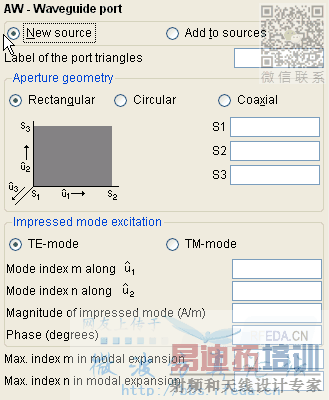
New source
New excitation, replaces all previous excitations.
Add to sources
Additional excitation, is added to previous excitations.
Label of the port triangles
Label of the triangular mesh elements in the mesh which represent the waveguide port. (If multiple solutions are defined in the same *.pre file, then the usage of the waveguide ports with respect to the label/s to which it/they are applied must be consistent for all solutions.)
Rectangular
A rectangular waveguide cross section is used, which is defined by three points S1, S2, and S3 as follows: S1 is an arbitrary corner point, and S2 and S3 are two corner points which define the waveguide sides  (from S1 to S2) and  (from S1 to S3). The direction in which the mode is launched is given by  .
Circular
A circular waveguide cross section is used. The point S1 denotes the centre of the circular port, and the point S2 specifies the radius and start point for the angular dependency. A further point S3 must be perpendicular above the centre of the circular plate, so that the direction from S1 to S3 indicates the direction in which the waveguide modes are launched.
Coaxial
Here a feed of a coaxial waveguide with circular cross sections of both the inner and outer conductor can be specified. The point definitions are the same as for the circular waveguide, except that an additional point S4 must be defined between S1 and S2 which specifies the radius of the inner conductor.
Excite fundamental mode
Select this option to automatically excite the fundamental mode of the waveguide can be excited. When this option is selected, the mode type and its indices (m and n) can not be specified since they are determined automatically.
TE-mode
If this option is checked, a TEm,n mode (also referred to as Hm,n) is used as excitation. This option is only available when "Excite fundamental mode" has not been selected.
TM-mode
If this option is checked, a TMm,n mode (also referred to as Em,n) is used as excitation. This option is only available when "Excite fundamental mode" has not been selected.
TEM-mode
If this option is checked (only available for the coaxial waveguide since TEM modes don't exist in rectangular/circular waveguides), a TEM mode is used as excitation. This option is only available when "Excite fundamental mode" has not been selected.
Mode index m
The index m of the TEm,n or TMm,n mode which is impressed at the port. Note that for a rectangular waveguide the index m is related to the  direction (i.e. from point S1 to S2). For a circular/coaxial waveguide, m denotes the angular dependency. This option is only available when "Excite fundamental mode" has not been selected.
Mode index n
The index n of the TEm,n or TMm,n, mode which is impressed at the port. Note that for a rectangular waveguide the index n is related to the  direction (i.e. from point S1 to S3). For a circular/coaxial waveguide, n denotes the radial dependency. This option is only available when "Excite fundamental mode" has not been selected.
Magnitude…
Absolute value of the complex amplitude of the impressed mode. For a TE-mode the unit is A/m, whereas for TM- or TEM-modes this is in V/m. Note that an amplitude of zero can also be specified. In this case a waveguide port is acting purely as a passive port (e.g. as waveguide termination), and no wave is launched.
Phase
The phase of the impressed mode in degrees.
Rotation angle  0
This option is available for circular and coaxial modes only and indicates the rotation angle in degrees by which a mode is rotated anti-clockwise with respect to the reference direction (point S2).
Modal expansion
At a waveguide port a specific mode is used as impressed excitation. However, due to discontinuities in the model, also higher order modes can result and will be propagating backwards through the port (applies to both active and passive ports). The maximum modal expansion indices taken into account during the calculation can be determined automatically by the kernel or specified manually. The included modes must be sufficient to capture the resulting field distribution of the problem. Note that the mesh across the waveguide port must be fine enough to represent the potential rapid field variation of included higher order modes. Also note that an increased number of higher order modes included in the model may have a significant impact on the run-time. If specified manually then the input values denote the maximum mode indices m and n which will be used to expand the backwards travelling waves. If determined automatically, then all propagating modes will be included, as well as evanescent modes that decay faster than  at a tenth of a wavelength away from the waveguide port.
Passive port only
The waveguide port can be marked as passive only so that it will not be considered during S-parameter calculations. In this case the port is acting purely as a passive waveguide termination, and the coupling to and from this port will not be calculated.
不知道怎么样添加混合模式进行激励,例如HE11模式可以使用TE11+TM11模式代替。不知道这样添加可以不?
圆波导那个S3是怎么定义的没看明白啊。
小编能否说说在CADFEKO中怎么设置Edge Port?
最好能提供个简单例子,谢了。
有道理。
CST微波工作室培训课程套装,专家讲解,视频教学,帮助您快速学习掌握CST设计应用
上一篇:哪里有feko 5.2 for linux的版本啊
下一篇:再介绍下FEKO吧。

