- 易迪拓培训,专注于微波、射频、天线设计工程师的培养
求教 cadfeko中使用UTD在什么地方设置
UTD/ GO Part
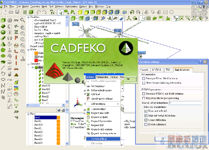
CADFEKO : solution --> solution --> The High frequency tab
The High frequency tab
The High frequency tab provides settings for the high-frequency asymptotic methods
available in FEKO (Physical optics、the UTD (uniform theory of diffraction) and Geometrical
optics for dielectrics).
Any changes to the high frequency settings should be based on the physical considerations
of each model.
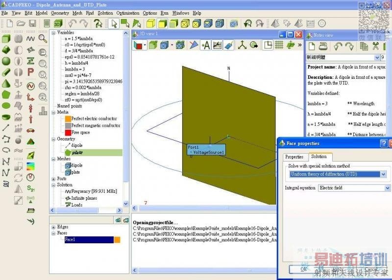
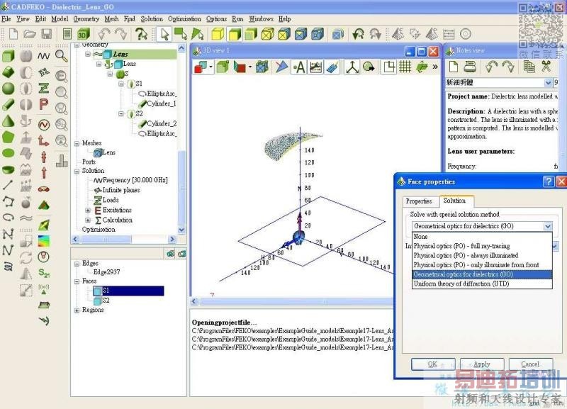
Solution using PO、UTD or GO is activated for each face (see section 5.7.1). If Decouple
PO and MoM solutions or Decouple UTD/GO and MoM solutions are checked、the PO
or UTD/GO structures are not taken into account when calculating the MoM currents.
In this case、for example、the input impedance of a horn fed parabolic reflector、where
the horn is solved using the MoM and the reflector using PO、will be the same as that
of the MoM horn in free space. In general、where the MoM and PO/UTD/GO regions
are electrically far apart、and far field quantities are of interest、decoupling the solutions
may save a significant amount of memory and run time without significantly affecting the
results.
During calculations using the PO formulation、a large amount of the time is spent in
determining which surfaces are illuminated from each source. This information may be
saved by activating the Store / re-use shadowing information to speed up subsequent runs
(re-use is only possible if the physical geometry of the model is unchanged). Storage of
the shadowing information、however、does lead to huge *.sha files on disk.
If Export ray file for post-processing is checked、FEKO outputs the rays used during a the
UTD or GO solution process to a *.ray file so that they may be viewed in POSTFEKO.
It should be noted that these files can be very large、especially when using a MoM /
UTD solution that has not been decoupled and there are more than a few hundred mesh
elements in the MoM region.
The Max. no. of ray interactions field limits the number of reflections/transmition interactions
taken into account for each ray that is tracked during the solution process. For
example、a ray path that includes a double diffraction and one reflection has three interactions、
or a path that includes a diffraction and three reflections has four interactions.
The options in the Select ray contributions group allow selection of the special UTD ray
interactions that are to be taken into account. (Note that some combinations go hand in
hand. For example、the contributions of edge and corner diffractions in the UTD solution
are usually of the same order and they should be switched on or off together.) Selecting
more contributions or increasing the number of ray interactions will increase both
accuracy and computation time. The chosen settings should therefore be a compromise
between accuracy and solution time.
11.44 UT card
With this command the parameters for the Uniform geometric theory of diffraction (UTD)
for polygonal plates and Geometrical optics for dielectrics (GO) are defined.
Uniform geometric theory of diffraction (UTD)
The method (UTD/GO) that is to be applied can be chosen.


CST微波工作室培训课程套装,专家讲解,视频教学,帮助您快速学习掌握CST设计应用
上一篇:请高手分析一下错误原因
下一篇:求助:怎么算室内场分布?

