- 易迪拓培训,专注于微波、射频、天线设计工程师的培养
Segment with same start and end points at
录入:edatop.com 点击:
Film contains DRC error(s).
Segment with same start and end points at
(882.917 1568.811) will be ignored. Increasing output
accuracy may allow segment to be generated.
设置如下图所示
是怎么回事啊!
Segment with same start and end points at
(882.917 1568.811) will be ignored. Increasing output
accuracy may allow segment to be generated.
设置如下图所示
是怎么回事啊!
Same Segment Start and End Point Warning
Reply How do I get rid of these warnings? They seem to happen with the edges of auto-generated fills. There are usually dozens of them on layers with ground fills. I've historically ignored them, but they are annoying me.
WARNING: Segment with same start and end points at
(8205.122 2561.020) will be ignored. Increasing output
accuracy may allow segment to be generated.
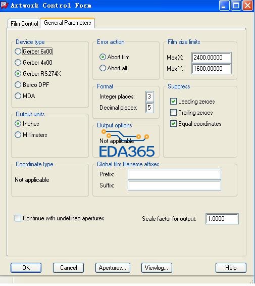
My design accuracy is 3 decimal places. My units of measure are mils. My RS274X gerber output accuracy is 5 decimal places.
--Mark
Post Points: 50
Fri, Oct 29 2010 7:48 AM
oldmouldy
Joined on Tue, Jul 15 2008
Woking, Surrey
Posts 1,138
Points 19,145
Re: Same Segment Start and End Point Warning
Reply You should get this reported to Cadence, or your Cadence VAR, to get this investigated futher. It might be configuration or design related but the Cadence folks should be able to get to the cause of the issue and come up with some resolution.
Post Points: 5
Fri, Oct 29 2010 11:29 AM
KEN13
Joined on Wed, Aug 6 2008
Barkhamsted, CT
Posts 99
Points 1,580
Re: Same Segment Start and End Point Warning
Reply Just a thought...by chance was anything brought in from AutoCad file. I know when I have worked between Layout to AutoCad to PCB Editor and had a square drawn translating to AutoCad it would add a dot at the end point of each line. Could this be the problem
Have a good day, Ken Capture 16.5 S022, Layout 16.2.0p001, PCB Editor 16.5 S025
Post Points: 5
Fri, Oct 29 2010 12:23 PM
Rik Lee
Joined on Tue, Dec 2 2008
HOME, SC
Posts 166
Points 2,715
Re: Same Segment Start and End Point Warning
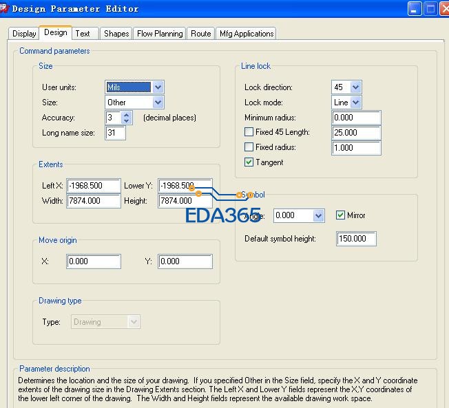
Answer Reply When you state that your desing has an accuracy of 3 do you mean that in the Design tab of the Design Parameter Editor the Accuracy = 3 or do you mean 0?
If your design is in MILS with an accuracy of 3 that equals .000001 inches and your output is 5 decimal places or .00001 inches which is one decimal place less than the design is at.
When using Raster based artwork you should use an accuracy in the design that will allow the artwork to generate the data without the possibility of rounding down. Generally the use of a MILS 1 database (.0001 inches) or equivilent will eliminate any problems with rounding down data.
Post Points: 20
Fri, Oct 29 2010 12:55 PM
melview1
Joined on Wed, May 20 2009
Shakopee, MN
Posts 41
Points 785
Re: Same Segment Start and End Point Warning
Reply Rik Lee, Accuracy = 3 in the Design Parameters Design Tab.
I changed it to Accuracy = 2 (accuracy of 0.00001" ) to match the 5 decimal place artwork accuracy (0.00001" ) and that got rid of the warnings. Now I just have to go back and fix the 171 DRC Errors that changing the accuracy generated.
Thank you very much. Life just got a bit easier.
--Mark
Post Points: 20
Sun, Oct 31 2010 9:21 AM
Rik Lee
Joined on Tue, Dec 2 2008
HOME, SC
Posts 166
Points 2,715
Re: Same Segment Start and End Point Warning
Reply Mark,
I'd suggest, when using raster artwork, that you desin in no greater than an accuracy of MILS 1 (.0001 inches). This will allow your artwork accuracy to generate data at the full precision of it's output without the possibility of rounding down data.
~Rik
这个format参数和NC parameters里面的要一致 不然就会有告警
谢谢 已解决。
mark下
Cadence Allegro 培训套装,视频教学,直观易学
上一篇:在ALLEGRO中能生成*.ASC文件吗?
下一篇:原理图的电源部分不懂,求指教