- 易迪拓培训,专注于微波、射频、天线设计工程师的培养
CST2013: Time Domain Solver Parameters
 Simulation: Solver
  Start Simulation
  Time Domain Solver
If you are not familiar with what the transient solver does and what it is used for, you should first read the Solver Overview or the Transient Solver Overview.
In this dialog, many important settings for a solver run can be set. Most of them have a strong influence on the calculation time. Also, an optimization run for your structure can be set up from here.
Solver settings frame
Mesh Type
This settings decides which solver to use. The transient solver is used when Hexahedral is selected, and the TLM solver is used when Hexahedral TLM is selected.
Accuracy
This setting defines the steady-state monitor. It influences the duration of the simulation. It is a value for the accuracy of the frequency domain signals that are calculated by Fourier Transformation of the time signals.
This setting must be understood only in connection with the processing of the time signals. Errors made by discretizing a structure can only be influenced by manipulating the mesh.
Every simulation stops at some time. This means that the signals that are calculated are truncated at this point, regardless of their values. If these values are non-zero, the Fourier Transformation will produce an error because only a part of the ”whole” signal with all of its non-zero values has been used for the transformation. Therefore, the ”smaller” the signals are, the more accurate the frequency domain values will be.
To get a value for the accuracy, the amplitudes of the time signals as well as the total energy inside the calculation domain are used. During the simulation, the total energy value is frequently calculated and related to the maximum energy that has been monitored thus far. You can find the corresponding energy curve in logarithmic scale in the 1D Results folder and the simulation stops when the defined accuracy level is reached. However, in some cases, the calculation may last a little bit longer due to the mentioned accuracy check of the time signals.
Store result data in cache
Check here if you want the solver results to be stored in the result data cache. The efficient usage of the result data cache is explained in the printed documentation "Advanced Topics".
Stimulation settings frame
Source type
Define here the type of excitation, choosing between ports and plane wave excitation. You make a selection only if some ports (waveguide or discrete ports) or a plane wave is defined in your structure. Further specifications of the different source types can be set in the corresponding dialog boxes Solve  Waveguide Ports / Discrete Ports / Plane Wave. You can select an existing or define a new reference Excitation Signal from the Navigation Tree or determine different signals for each selected port separately.
Plane Wave: This selection starts a plane wave excitation.
All ports / Selected ports / Port X: Selecting a port excitation also determines which S-parameter will be calculated. If All ports is selected, the simulation is repeated such that each defined port will be stimulated once. With this setting, all N*N elements of the S-parameter matrix of your device will be calculated. In contrast to this, if one specific port is chosen to be stimulated, only N S-parameters of an N-port device are calculated. An exception of this rule is a loss-free two-port device, where all its S-parameters are computed in only one simulation run. In this situation, the fact that the matrix is symmetric for all loss free structures is taken advantage of. The corresponding modes can be selected below.
Finally, it is possible to define a specific selection of port modes by opening the Port mode list... dialog. Here, each port mode is listed separately and can be marked for calculation. The simulation runs are then performed one after another. However, it is also possible to choose a simultaneous excitation of the selected port modes with different excitation signals.
Example:
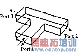
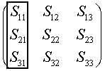
| Here, the complete S-Parameter matrix for the 3-Port is shown. The items that would be calculated if port 1 was chosen to be stimulated are marked by the black box.
In fact, S12 and S13 are implicitly calculated as well because of the symmetry of the matrix. |
Mode: Chooses the number X of the mode that will be used for the stimulation. Usually, the S-parameters are calculated for the fundamental mode (number 1) only, the selection All excite each mode separately. Please note that the calculated S-parameters depend on the selected mode.
Inhomogeneous port accuracy enhancement
This check button enables the port accuracy enhancement functionality for QTEM modes at inhomogeneous ports. Because of an existing inhomogeneity in the port region, the waveguide operator works less accurately with increasing distance from the port mode calculation frequency. Depending on the grade of inhomogeneity and the range of the bandwidth, this may lead to a broadband error in the simulation results. If this error becomes significantly large, it can be removed by applying the inhomogeneous port accuracy enhancement functionality. However, please note that the excitation of all port modes are required for this procedure, so it is advisable to activate this functionality carefully and, if possible, together with the usage of S-parameter symmetries.
Consequently, activating this check button implies that the source type is set automatically to All ports / All modes. If some inhomogeneous ports occur in the structure, the port modes will be calculated together with broadband information that is added to the result tree. After all solver runs are finished, the complete S-parameter matrix is generated considering the broadband behavior of the dispersive port modes. The number of frequency samples for this procedure may be defined in the Special Solver Parameters - Waveguide dialog.
Please note that this button applies for QTEM modes only; for inhomogeneously filled waveguides, refer to the broadband port functionality in the Special Solver Parameters - Waveguide dialog.
See also the Waveguide Port Overview page for further detailed information concerning inhomogeneous ports.
Calculate modes only
Calculates solely the port modes of your structure, i.e., no transient solver run is performed.
Superimpose plane wave excitation
This check button activates the superimposed stimulation of a previously defined plane wave in addition to a usual S-Parameter calculation. As excitation source type one or more port modes are selected as described above and the plane wave stimulation is then applied in addition without producing any plane wave specific output files. Consequently the energy contribution of the plane wave excited into the calculation domain influences the S-Parameter and balance results possibly showing some active behavior. Please note that the reference signal is used for exciting the plane wave.
S-parameter settings frame
Normalize to fixed impedance: S-Parameters are always normed to a reference impedance. You may either select to norm them to the calculated impedance of the stimulation port or you may specify a number of your choice.
S-parameter symmetries: Selecting this check button activates the S-parameter symmetry settings made in the S-parameter List... dialog box. These settings should be made due to occurring structure symmetries to save simulation time. The solver only starts the necessary calculation runs; the remaining results will be copied, including time signals. The symmetry conditions are only applied to the selected port mode stimulations.
Adaptive mesh refinement frame
Adaptive mesh refinement: Mark this check box to activate the adaptive mesh refinement. The mesh will be adaptively optimized by either adding extra grid lines due to the calculation of the electromagnetic field energy or by successively changing the settings of the mesh expert system. Press the Adaptive Properties... button to edit the current settings for the mesh refinement.
Sensitivity analysis frame
Use sensitivity analysis: Mark this check box to run the sensitivity analysis. In this case the derivative of all simple parameters are calculated for the transient solver run. The results (e.g. derivative of the S-parameter with respect to a design parameter) can be accessed via the 1D Results in the Navigation Tree..
Press the Properties... button to choose the sensitivity analysis parameters.
For a more detail description see the sensitivity analysis overview page.
Start
Calculates the port modes and starts the time domain calculation.
Optimize...
This button opens a dialog box that allows you to set up and start an optimization run.
Par. Sweep...
Opens the parameter sweep dialog.
Acceleration...
Opens the acceleration dialog box to control the high performance options of the simulation run (e.g. GPU acceleration, Distributed Computing, MPI).
Specials...
This button leads to a dialog where further special settings for the solver can be made. The settings are for expert users only and should generally not be changed.
Simplify Model...
Opens the simplify model dialog.
Apply
Stores the current settings. The dialog box remains open.
Close
Closes this dialog box without performing any further action.
Help
Shows this help text.
See also
Solver Overview, Transient Solver Settings Overview, Special Solver Settings, Waveguide Ports, Frequency Range Setting, Optimizer, Signals in Time Domain Simulations Overview , Plane Wave , S-Parameter Symmetries, Port Mode Excitation Selection, Excitation Signal, Distributed Computing, MPI Simulation Overview, Excitation Source Overview, Excitation Source Overview, Sensitivity Analysis Overview
 最全面、最专业的CST微波工作室视频培训课程,可以帮助您从零开始,全面系统学习CST的设计应用【More..】
频道总排行
- CST2013: Mesh Problem Handling
- CST2013: Field Source Overview
- CST2013: Discrete Port Overview
- CST2013: Sources and Boundary C
- CST2013: Multipin Port Overview
- CST2013: Farfield Overview
- CST2013: Waveguide Port
- CST2013: Frequency Domain Solver
- CST2013: Import ODB++ Files
- CST2013: Settings for Floquet B


