- 易迪拓培训,专注于微波、射频、天线设计工程师的培养
CST2013: Make Voltage Monitor From Curve
录入:edatop.com 点击:
Simulation: Monitors Voltage Monitor
A voltage monitor from a curve can be defined for time domain calculations only.
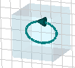
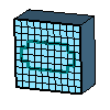
The ”Make Voltage Monitor From Curve” dialog box appears if a curve item has been selected in the Voltage Monitor Mode. This curve defines the path of the voltage monitor. However, because the fields are known exactly only on grid edges, a grid mapped version of the path will be used for the integration rather than the original path. Change to the mesh view to see the mapped path.
|
|
A curve item inside of a structure. | The same curve item, mapped on the grid. This path is used for the integration of the electric fields.
|
The results of a voltage monitor are accessible through the 1D Results folder of the navigation tree. There, the time dependent signals and their Fourier-transformed frequency dependent representation can be accessed.
Name
In this text field, the name of the voltage monitor can be specified.
Invert orientation
Every curve item has its own orientation. In the main view, it is visualized by a small arrow somewhere on the curve. Mark this check button to invert the orientation. Inverting the orientation results in a negation of the time signals.
OK
Creates the voltage monitor and closes the dialog.
Cancel
Closes this dialog box.
Help
Shows this help text.
CST微波工作室培训课程套装,专家讲解,视频教学,帮助您快速学习掌握CST设计应用
上一篇:CST2013: Monostatic RCS Sweep Properties
下一篇:CST2013: MPI Cluster
CST培训课程推荐详情>>
 最全面、最专业的CST微波工作室视频培训课程,可以帮助您从零开始,全面系统学习CST的设计应用【More..】
频道总排行
- CST2013: Mesh Problem Handling
- CST2013: Field Source Overview
- CST2013: Discrete Port Overview
- CST2013: Sources and Boundary C
- CST2013: Multipin Port Overview
- CST2013: Farfield Overview
- CST2013: Waveguide Port
- CST2013: Frequency Domain Solver
- CST2013: Import ODB++ Files
- CST2013: Settings for Floquet B


