- 易迪拓培训,专注于微波、射频、天线设计工程师的培养
CST2013: Vertical and Horizontal Polarization
The vertical and horizontal polarization is often requested to be visualized in a farfield plot. Because the vertical or horizontal orientation of the polarization is related to the position of the antenna structure, it is just a matter of adequately choosing the coordinate system. The default coordinate orientation can be changed in the Farfield Plot Special Settings to define a new local reference system. Afterwards, the available phi and theta components enable the visualization of vertical or horizontal polarization parts, yet only at some special locations in space. The relevant facts to be considered in this context are demonstrated in the following by a short example.
Absolute Value | Description |
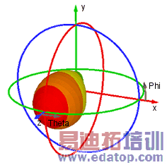
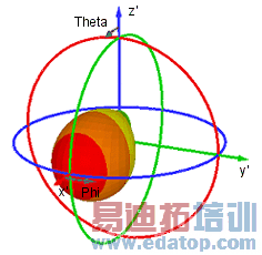
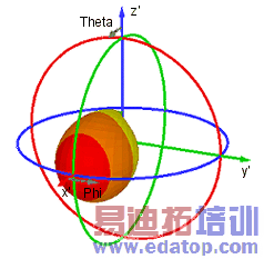
| On the left, the farfield result of an antenna structure is shown having its main lobe in the z-direction that represents the north pole of the system’s orientation. However, as you can see in the pictures below, due to the default coordinate system the plots of the phi and theta component barely give an impression of the polarization orientation at the main radiation direction. |
|
|
Theta Component | Phi Component |
|
|
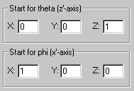
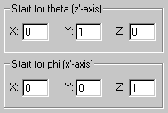
To enable a somehow more plausible visualization, the local coordinate system in the Farfield Plot Special Settings is changed in an appropriate way. Regarding the farfield orientation, the new z’-axis is now represented by the y-axis defining the start for the angle theta and analogous the new x’-axis is given by the z-axis defining the start for the angle phi:
Change of the Local Coordinate System | ||
| ||
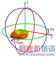
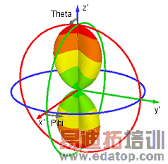
In the 3D plots, the new coordinate axes x’, y’ and z’ are marked by a stroke and are displayed in the farfield plot for a better understanding. As a result of the system’s rotation, the farfield plots of the phi and theta components have changed in a relevant manner, while the lobe of the absolute value has remained the same as before.
Absolute Value | Description |
| The main lobe of the antenna structure is now positioned in the x-direction. As you can see in the pictures below, the theta component is quite similar to the absolute value and consequently the phi component is extremely small. (Note that different scaling factors are used for the two plots and thus the colors are misleading in direct comparison.) Now, regarding the main lobe (theta=90°, phi=0°), the theta and phi components represent exactly the vertical and horizontal polarization. Therefore, assuming that in practice the antenna radiates in x'-direction, we see that the main part of the field is vertically polarized. |
|
|
Theta Component | Phi Component |
|
|
CST微波工作室培训课程套装,专家讲解,视频教学,帮助您快速学习掌握CST设计应用
上一篇:CST2013: Frequency Domain Solver Overview - Resonant: S-Parameter, fields
下一篇:CST2013: Parametric Result Properties
 最全面、最专业的CST微波工作室视频培训课程,可以帮助您从零开始,全面系统学习CST的设计应用【More..】
频道总排行
- CST2013: Mesh Problem Handling
- CST2013: Field Source Overview
- CST2013: Discrete Port Overview
- CST2013: Sources and Boundary C
- CST2013: Multipin Port Overview
- CST2013: Farfield Overview
- CST2013: Waveguide Port
- CST2013: Frequency Domain Solver
- CST2013: Import ODB++ Files
- CST2013: Settings for Floquet B

