- 易迪拓培训,专注于微波、射频、天线设计工程师的培养
CST2013: Cutting Plane
 View: Sectional View
  Cutting Plane
 Properties
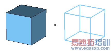
In this dialog box you can set a cutting plane for your structure. The structure will be hidden, left as wire frame or set to transparent at the upper side of the cutting plane and left as before below the cutting plane. Thus you will be able to have a look inside your structure.
Cutplane control frame
Use cutplane: Switch off the structure cutting plane.
Align cutplane with axis: Use the structure cutting plane, aligning it to the standard (XYZ) coordinate system.
Align cutplane with WCS : Use the structure cutting plane, aligning it to the local (WCS) coordinate system.
Free cutplane control: Use the structure cutting plane with the previously set alignment and make the rotation and pitch sliders (see below) available. Also a 'help' plane will be visualized, marking the normal and the 'up'-direction of the plane to help with orientation.
Axis: Align the cutting plane with respect to the chosen control mode. (e.g. in axis-aligned mode choose 'X' to align it with the YZ-plane)
Location
Position slider: Move the cutting plane along the plane normal.
Note: In 'axis aligned control' mode the indicated position is the spatial plane position on the respective axis. In any other mode the indicated position is calculated with respect to the slider position. (Slider at 50% has always an indicated position of 0.0, which marks the center of the range in which the plane can be moved; slider above or below 50% will make the indicated position give the spatial distance to the center of a.m. range)
Rotation slider: Rotate the cutting plane around the up-vector which is indicated on the 'help' plane (see 'Free cutplane control' mode). Angle is given in degrees.
Note: Only available in 'Free cutplane control' mode (see above).
Pitch slider: Rotate the cutting plane with the up-vector which is indicated on the 'help' plane (see 'Free cutplane control' mode). Angle is given in degrees.
Note: Only available in 'Free cutplane control' mode (see above).
By Index: If you select this option, the cutting plane can only be set on mesh planes. Also the output of the plane location shows the mesh index rather than the spatial location of the cutting plane. This setting can only be used if a valid mesh is already created.
Note: This option is only available for hexahedral meshes with 'axis aligned control' mode (see above).
Appearance of part above cutplane frame
Changes the appearance of the removed part of your structure.
Hide: Don’t display the removed part at all.
Wireframe: Display it as wire frame.
Transparent: Display it as transparent.
Solid: Display the removed part, but also shows the cutting plane.
Note that this setting will not be used if you have activated the Wireframe in View: Options  View Options (
 ) – General or clicked the View: Visibility
 Wire Frame (
 ) control. If the fields are displayed on a 2D plane and the Transparent shapes in field plot mode is activated this frame is disabled.
Options frame
Transparent shapes in field plot mode: Display all the shapes transparent when the field plot mode is activated.
Draw 2D when cut plane is active: Display the structure in a flat and true 2D style.
Draw solid cutplane: If this field is checked, the cutting plane will be displayed as solid in the shapes color. Otherwise it will be transparent.
2D fields on selected shapes only: Draw cutlines and 2D fields only for the selected shapes for a better performance or visibility.
Cutplane location in selected shape only: Move the cutting plane relative to the selected shape only. This feature offers you a better cutting plane handling for small details within bigger structures.
Close
Closes this dialog box.
Apply
Applies any changes to the visualization. Only active if changes in the edit fields have been made.
Help
Shows this help text.
CST微波工作室培训课程套装,专家讲解,视频教学,帮助您快速学习掌握CST设计应用
上一篇:CST2013: Cover Planar Curve
下一篇:CST2013: Create an Ellipse
 最全面、最专业的CST微波工作室视频培训课程,可以帮助您从零开始,全面系统学习CST的设计应用【More..】
频道总排行
- CST2013: Mesh Problem Handling
- CST2013: Field Source Overview
- CST2013: Discrete Port Overview
- CST2013: Sources and Boundary C
- CST2013: Multipin Port Overview
- CST2013: Farfield Overview
- CST2013: Waveguide Port
- CST2013: Frequency Domain Solver
- CST2013: Import ODB++ Files
- CST2013: Settings for Floquet B
